I.B. 17555C
Effective November 1999
Page A2
3.2 DIGITRIP 3001 DRAWOUT RELAY PARTS LIST
BEFORE MOUNTING THE DRAWOUT RELAY,
REVIEW TABLE 3 FOR ALL OF THE INCLUDED
PARTS:
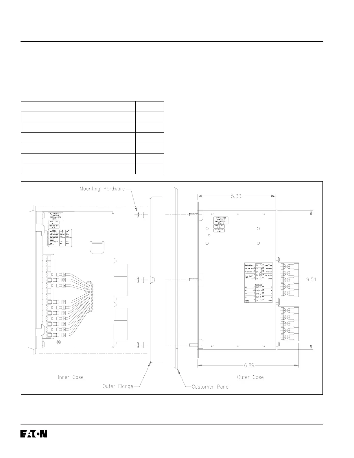
3.3 MOUNTING THE DRAWOUT OUTER CASE
3.3.1 The DT3001 Drawout Relay mounts in the exact
same mounting holes as a standard DT3000.
3.3.2 Remove the Drawout Inner Chassis from the
outer case.
3.3.3 Refer to Figure A-3 below. Place the outer case
flush against the backside of the panel so that
the case studs project through their respective
holes.
3.3.4 The plastic outer flange is seated on the front of
the panel and is attached to the top, center, and
bottom studs that protrude through the panel.
3.3.5 Use the #10-32 hex nuts and lock washers,
included with the relay, to mount the unit on the
panel.
Fig. A-2 DT3001 Panel Mounting
TABLE A-3 DT3001 DRAWOUT RELAY PARTS LIST
Description Quantity
Digitrip 3001 Drawout Inner Chassis 1
Digitrip 3001 Drawout Outer Case 1
Outer Flange 1
Mounting Hardware – #10-32 nuts & lock washers 6 each
Digitrip 3001 Instruction Book – I.B. 17555 1
Drawout Relay Addendum to I.B. 17555 1
 Loading...


