I.B. 17555C
Effective November 1999
Page A3
4.0 WIRING AND SETUP
WARNING
ENSURE THAT THE INCOMING AC POWER
SOURCES ARE DISCONNECTED BEFORE PER-
FORMING ANY WORK ON THE DIGITRIP 3001
PROTECTIVE RELAY OR ITS ASSOCIATED EQUIP-
MENT. FAILURE TO OBSERVE THIS PRACTICE
COULD RESULT IN SERIOUS INJURY, DEATH AND/
OR EQUIPMENT DAMAGE.
NOTE: The following material replaces section 5-4,
on page 35.
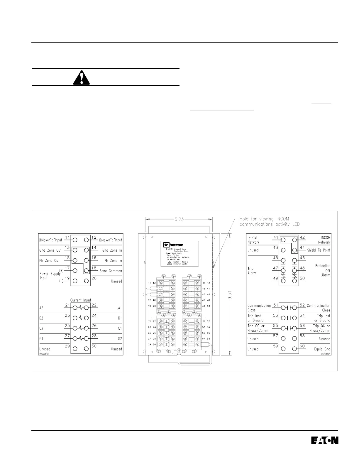
Refer to Figures A-5, A-6, A-7, and A-8 for the DT3001
typical wiring diagrams. Note the following:
4.1 Direct wire connections to the terminal blocks must
be sizes #14 AWG to #10 AWG.
The appropriate sized spade and ring lugs can also
be used to accommodate the wires.
4.2 All contacts are shown in the de-energized position.
NOTE: The Protection Off Alarm Relay is energized
when control power is applied and the DT3001 is
operating properly. To obtain a contact that closes
when protection is lost, use terminals 48 & 50. For a
contact that opens when protection is lost, use
terminals 46 & 48.
4.3 The Digitrip 3001 comes with the zone interlocking
jumpers installed (terminals 13 to 14 and 15 to 16).
Leave these jumpers in place if zone selective inter-
locking is not used. See Section 5 below for more
information on this topic.
4.4 The INCOM communications LED can be seen
through a hole in the outer chassis. Refer to Figure
NOTE: All wiring must conform to applicable federal,
state, and local codes.
Fig. A-3 Rear View of DT3001 Drawout Outer Case
 Loading...


