I.B. 17555C
Effective November 1999
Page A6
5.0 APPLICATION CONSIDERATIONS
NOTE: The following material replaces Figure 4-1 and
4-2 on pages 32 and 33.
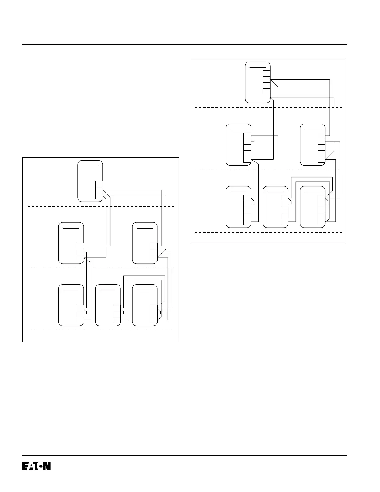
Zone selective interlocking is available on the Digitrip
3001 Protective Relays for the inverse time and short
time functions on the phase and ground elements. Refer
to Figure A-8 for a typical phase zone selection interlock-
ing wiring diagram or Figure A-9 for a typical ground zone
interlocking wiring diagram. The terminal numbering is
different from that of the standard DT3001 Protective
Relay.
Fig. A-8 Typical Phase Zone Selective Interlocking
Connection Diagram
Fig. A-9 Typical Ground Zone Selective Interlocking
Connection Diagram
NOTES:
1. Maximum distance between first and last phase or
ground zone interconnection cable should be 250
feet. Route separate from power conductors.
2. Jumper on devices in last zone used to provide time
delay per inverse time overcurrent or short delay time
setting. If jumper is not used the Digitrip 3001 will ini-
tiate trip without time delay (nominally 0.1 seconds).
3. Up to 10 Digitrip devices may be wired in parallel to
provide a single upstream restraint signal.
4. Only one zone common used for both phase and
ground.
5. DO NOT CONNECT ZONE COMMON TO EARTH
GROUND.
DT3000
M
Typical Main
Digitrip 3000
ZONE 1
ZONE 2
ZONE 3
Typical
Feeder
DT3000
Typical
Downstream
Breaker
DT3000
15
Phase
Out
In
Zone Com.
16
18
DT3000
F1
15
16
18
DT3000
F2
15
16
18
DT3000
B1
15
16
18
DT3000
B2
15
16
18
DT3000
B3
15
16
18
DT3000
M
Typical Main
Digitrip 3000
ZONE 1
ZONE 2
ZONE 3
Typical
Feeder
DT3000
Typical
Downstream
Breaker
DT3000
15
Ground
Out
In
Zone Com.
16
18
14
13
DT3000
F1
15
16
18
14
13
DT3000
F2
15
16
18
14
13
DT3000
B1
15
16
18
14
13
DT3000
B2
15
16
18
14
13
DT3000
B3
15
16
18
14
13
 Loading...


