12 Eaton Ferrups FX UPS P-164000906 Eaton Ferrups FX User’s Guide P-164000906—Rev 05
IMPORTANT
FOR U.S. INSTALLATIONS, READ THIS IMPORTANT NOTE
• The mm² and AWG wire size for each circuit breaker size shown on the wiring diagrams. The minimum
recommended circuit breaker sizes for each model and voltage application are listed on the wiring
diagrams.
• Conductor sizes shall be no smaller that the 75°C wire size based on the ampacities given in Table 310.15
(B) of the Electrical code® (NEC®) ANSI/NFPA 70–2020, and article 220. All circuit conductors, including
the neutral conductor, must be the same size ( ampacity ) wire. Code may require a larger AWG size than
shown in this table because of temperatures, number of conductors in the conduit, or long service runs.
Follow local code requirements.
44..33 UUPPSS TTeerrmmiinnaall CCoonnnneeccttiioonnss
UPS AC Power Terminal Access
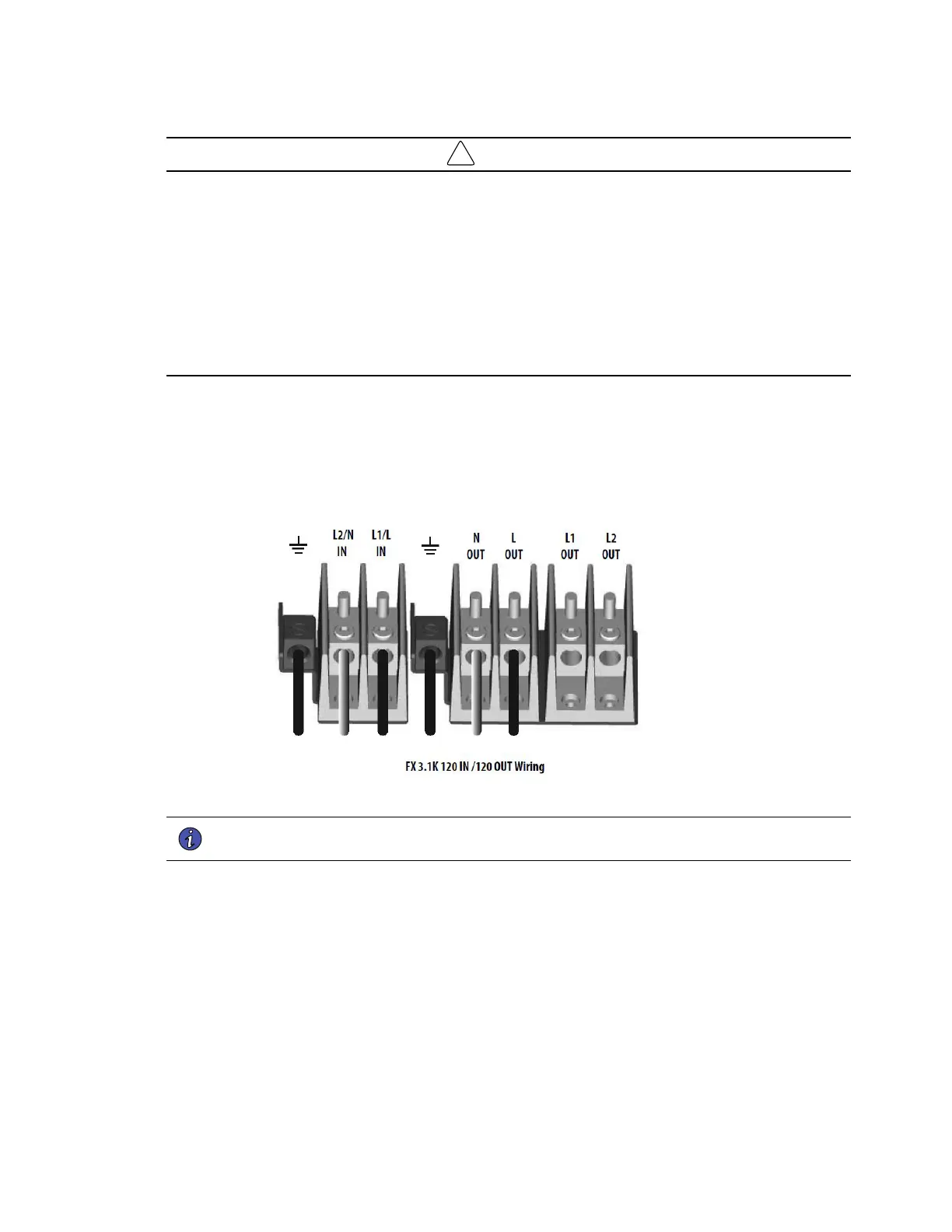
Figure 5. FX3100 120 Vac Input and 120 Vac Output Terminal Block Wiring
NOTE UPS Input and Output circuits must be installed in separate conduit systems and not
shared with other electrical circuits.
1. Remove the wiring access cover from the back of the UPS.
2. Install the proper input and output strain relief connectors into the wiring access cover.
3. Insert the L1, L2 N and G cable ends thru the wiring access cover into the applicable terminal slots in the
terminal block.
4. Secure the cables by screwing down the lug screws.
5. Reinstall the wiring access cover and ensure strain relief connections are secure.
UPS Terminal Connections
 Loading...