Eaton Ferrups FX UPS P-164000906 Eaton Ferrups FX User’s Guide P-164000906—Rev 05 15
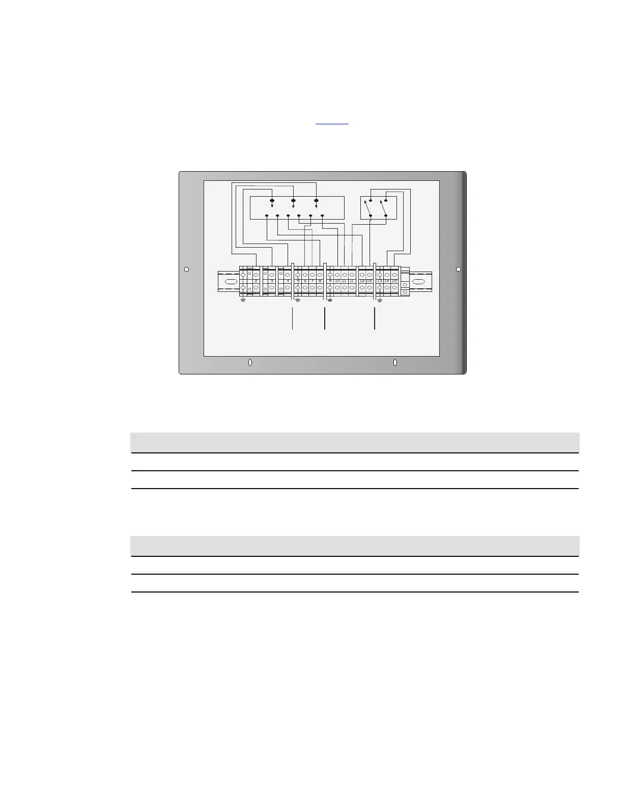
9. Find the terminal strip inside the bypass switch. Using the label on the back of the bypass switches lower
front cover panel, wire the terminal strip and tighten all connections securely. use copper wire and the
appropriate wire size for the current. See Figure 8 .
Figure 8. BPE External Bypass Switch Terminal Wiring Label
L1
L1
L1
L1
L1
L1
L2
N
L2
N
L1
L1
N
NC
N
NC
N
NC
L2
N
L2
N
AC TO UPS
PROTECTED
LOADS
AC FROM
UPS OUTPUT
AC LINE INPUT
AC TO
UPS INPUT
BPE-02, BPE-04, and BPE-05
208/240 Inputs
120 Input
** ALL GROUNDS TIED
THROUGH DIN MOUNTING
RAIL AND ARE BONDED
TO CHASSIS GROUND.
** INSTALLATION
TO BE PERFORMED
BY A QUALIFIED
ELECTRICIAN.
Table 7. Available Make Before Break Bypass Switch Models
Model Number
Ratings (UL/CSA) Continuous
Ratings (TÜV) Continuous
BPEFXMBB02 40A/300 Vac 50A/300 Vac
BPEFXMBB04 80A/300 Vac 80A/300 Vac
BPEFXMBB05 104A/300 Vac 120A/300 Vac
Table 8. Available Break Before Make Bypass Switch Models
Model Number
Ratings (UL/CSA) Continuous
Ratings (TÜV) Continuous
BPEFXBBM02 40A/300 Vac 50A/300 Vac
BPEFXBBM04 80A/300 Vac 80A/300 Vac
BPEFXBBM05 104A/300 Vac 120A/300 Vac
44..55 BBPPEE BByyppaassss SSyysstteemm WWiirriinngg DDiiaaggrraammss
The following notes are referenced by their number in the UPS external bypass wiring diagrams. Refer to the correct wiring
diagram for correct installation.
BPE Bypass System Wiring Diagrams
 Loading...