4
INM MTL SUM5 Rev 7
DRAFT - 09 June 2021 DRAFT - 09 June 2021
2.2.1 PSU/Common Services Card
• The PSU/Common Services Card is located in the right hand card slot of the
enclosure, (Position 0), when viewed from the front.
• As PSU/Common Service cards can be powered from 85-263VAC 50/60 Hz
or 88 to 300VDC for safety reasons please ensure the supply is fully isolated
before removing the associated card.
• Single and Dual redundant power supply options are available providing
secure power to the panel. For further information please see pages 17
and 18
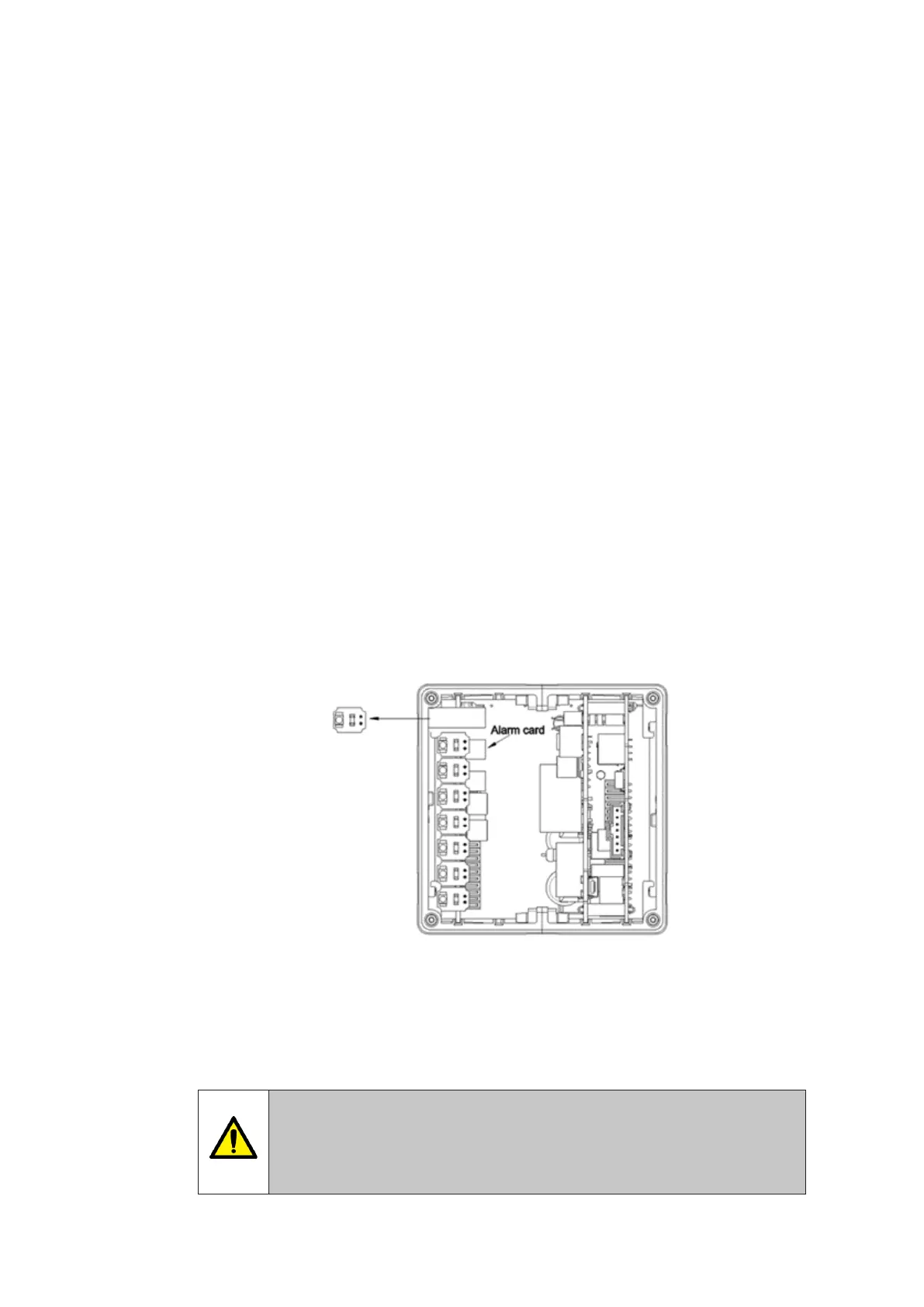
2.2.2 Alarm Cards (8 Channel)
• Alarm cards are located to the left of the PSU/Common Service card.
• On 16, 24 and 32 way versions multiple alarm cards are used.
• The alarm cards are interchangeable however as the associated
conguration settings are stored on the individual cards if a card is placed in
the incorrect slot the setting may not match the monitored process.
• The PSU/Common Services card and Alarm card are polarised to prevent
insertion into the incorrect card slot.
2.2.3 Pluggable LED’s
Each channel is illuminated by a pluggable LED located on the front of each 8 channel
alarm card.
The LED assembly is held in place by 2 pins and the assembly can be removed by pulling gently
towards you.
LED assemblies are available in the following colours:-
• White .........(WT). • Red ............(RD).
• Yellow ........(YW). • Green .........(GN).
• Blue ............(BL). • Intermixed …….(I).
(Specify colour required per channel).
WARNING !
Hazardous voltages may exist on the LED assembly connections accessed via
the frtont panel. Take care and use insulated tools to remove and replace
LED assemblies
 Loading...