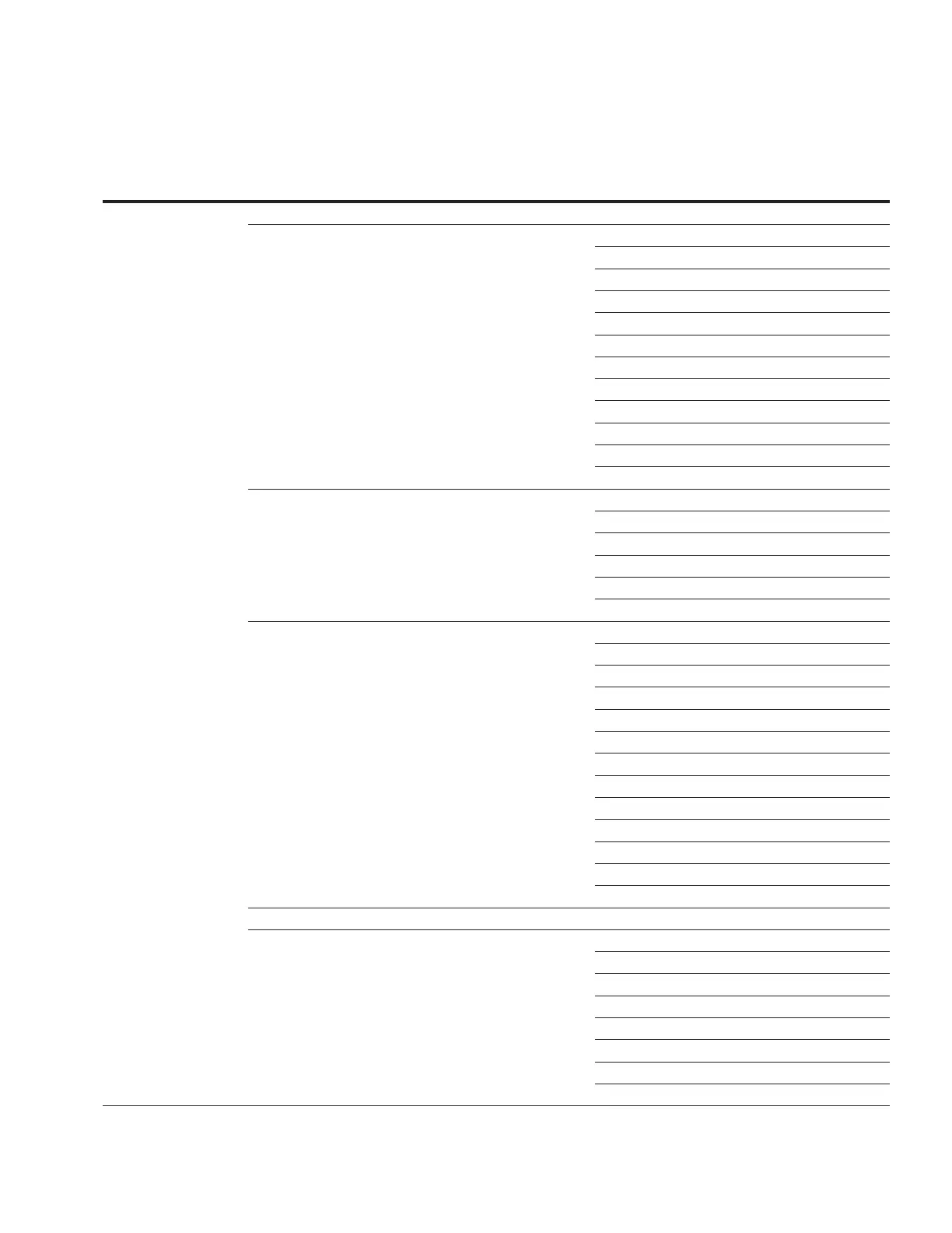
Table9. Function menu (continued)
Level 1
Main Menu
Level 2
Sub-Menu
Level 3
Sub-Menu
Level 4
Sub-Menu Parameter
Function
Code
*DIAGNOSTICS *Test LEDs (No Items) ---
*Control Firmware Version 920
Firmware Database Version 921
FPGA Version 922
Digital Hardware Revision 923
BootUtility Version 924
BootLoader Version 925
USB Device Connected 088
Factory Mode 088
Extended Comms Status 088
Config. Logic Equation Error 088
Self-Test 091
Last Self-Test Results 091
*Communications Comm Port #1 Tx Messages 260
Comm Port #1 Rx Messages 261
Comm Port #1 Rx Errors 262
Comm Port #2 Tx Messages 263
Comm Port #2 Rx Messages 264
Comm Port #2 Rx Errors 265
*Maintenance Contact Duty Cycle Monitor 333
PMT™ Mode A State 300
PMT Mode A Countdown Delay 301
PMT Mode A Time Delay 302
PMT Mode A Issue Test 303
PMT Mode B State 320
PMT Mode B Countdown Delay 321
PMT Mode B Time Delay 322
PMT Mode B Start Time 323
PMT Mode B Stop Time 324
PMT Mode B Max Deviation 325
PMT Mode B Current Limit 327
PMT Mode B Issue Test 328
*Sync Counters Tap Position Sync Count 110
_Metering PLUS Comp Voltage ---
Load Voltage ---
Load Current ---
Tap Position ---
LF TPI TRG STATUS ---
Max Deviation ---
Reg TPI CompV BandE ---
sV Src Load Comp ---
45
INSTALLATION, OPERATION, AND MAINTENANCE INSTRUCTIONS MN225003EN April 2018
CL-7 Voltage Regulator Control
 Loading...


