EasyManuals Logo
Home>ECS>Motherboard>H55H-I

ECS H55H-I User Manual

ECS H55H-I
74 pages
To Next Page IconTo Next Page
To Previous Page IconTo Previous Page
Page #25 background imageLoading...
Page #25 background image
21
Installing the Motherboard
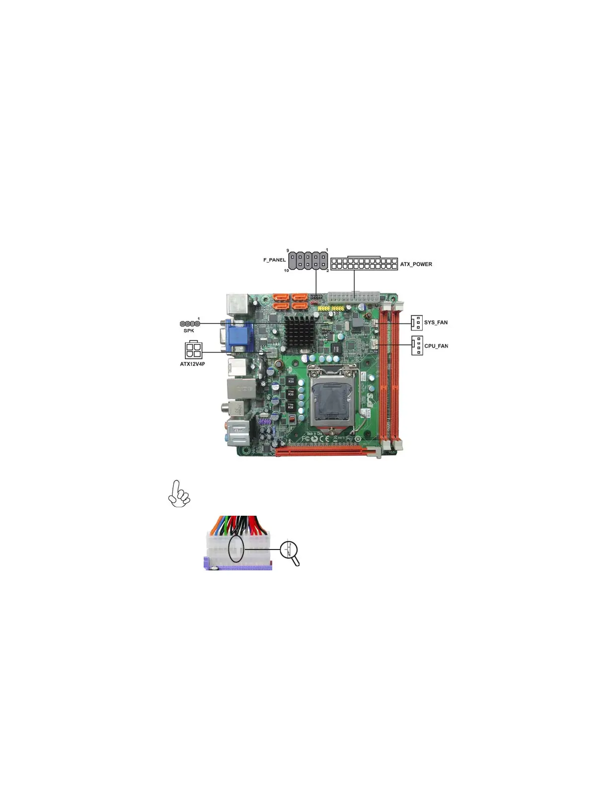
Connecting Case Components
After you have installed the motherboard into a case, you can begin connecting the
motherboard components. Refer to the following:
1 Connect the CPU cooling fan cable to CPU_FAN.
2 Connect the standard power supply connector to ATX_POWER.
3 Connect the case switches and indicator LEDs to the F_PANEL.
4 Connect the system cooling fan connector to SYS_FAN.
5 Connect the auxiliary case power supply connector to ATX12V4P.
6 Connect the case speaker cable to SPK.
The ATX_POWER 24-pin connector allows you to connect to ATX v2.x
power supply.
With ATX v2.x power supply, users please
note that when installing 24-pin power
cable, the latches of power cable and the
ATX_POWER match perfectly.
Connecting 24-pin power cable
24-pin power cable

Table of Contents

Questions and Answers:

Question and Answer IconNeed help?

Do you have a question about the ECS H55H-I and is the answer not in the manual?

ECS H55H-I Specifications

General IconGeneral
Number of memory slots2
Maximum internal memory8 GB
Supported memory clock speeds1066, 1333 MHz
Processor socket-
Compatible processor seriesIntel Core i3, Intel Core i5
S/PDIF out connectorYes
Number of SATA connectors4
Number of Parallel ATA connectors0
USB 2.0 ports quantity6
Audio chipRealtek ALC892
Power source typeATX
Audio output channels- channels
Motherboard form factormini ITX
On-board graphics cardNo
Parallel processing technology supportNot supported
LAN controllerRealtek RTL8111D(L)
Networking featuresGigabit Ethernet
BIOS typeAMI
BIOS memory size64 Mbit
Weight and Dimensions IconWeight and Dimensions
Width170 mm

Related product manuals