17
CAUTION
These models are designed and certified
for use with natural or propane gas.
For natural gas, the pressure regulator on
the header is set to 8” w.c. (20 mbar).
For Australia: the gas pressure regulator supplied with the
appliance must be fitted to the appliance inlet.
Adjust the test point pressure with one burner operating at
maximum setting as follow:
Models N9E
• 0.95 KPa for Natural gas
• 2.65 KPa for Propane gas.
Models N7E
• 1.0 KPa for Natural gas
• 2.65 KPa for Propane gas.
E.6.6 Conversion to another type of gas
Nozzle Table “B“ (see Appendix) gives the type of nozzles to
be used when replacing those installed by the manufacturer
(the number is stamped on the nozzle body).
At the end of the procedure, carry out the following check-list:
1. burner nozzle/s replacement
2. correct adjustment of primary air supply to burner/s
3. pilot nozzle/s replacement
4. minimum flame screw/s replacement
5. correct adjustment pilot/s if necessary
6. correct adjustment of supply pressure (see technical data/
gas nozzles table)
7. apply sticker (supplied) with data of new gas type used
E.7 Gas appliances regulations
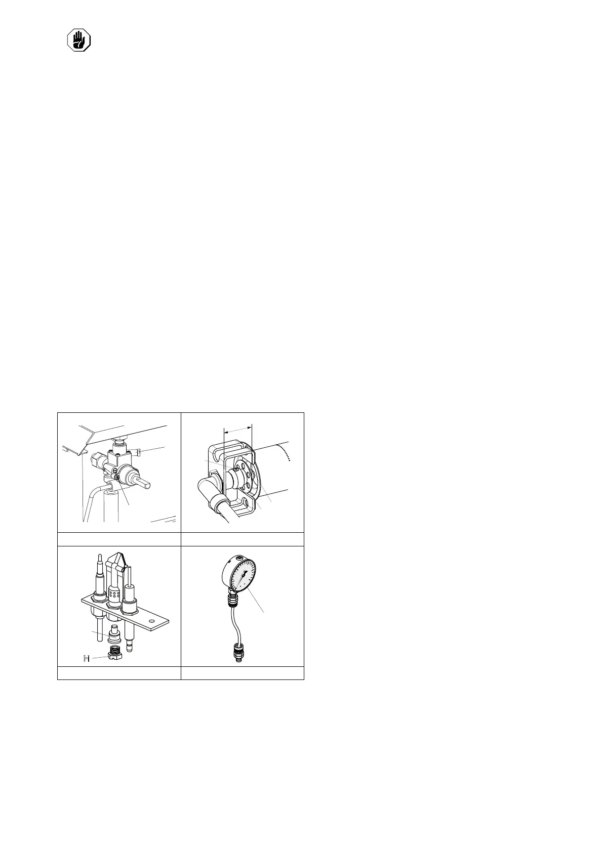
FIG. 1 FIG. 2
FIG. 3 FIG. 4
E.7.1 Supply pressure check (all versions)
Make sure the appliance is suitable for the type of gas
available, according to that given on the dataplate (otherwise,
follow the instructions given in E.6.6 Conversion to another
type of gas paragraph of this section).
The supply pressure must be measured with the appliance
operating, using a pressure gauge (min. 0.1 mbar).
1. Remove the control panel;
2. Remove screw “N“ from the pressure point (see FIG. 1);
3. Connect the pressure gauge “O“ (see FIG. 4).
4. Compare the value read on the pressure gauge with that
given in Table “B“ (see Appendix);
If the pressure gauge gives a reading outside the range of
values in Table “B“ (see Appendix), do not switch the
appliance on.
Consult the gas company.
E.7.2 Primary air checking
The primary air is correctly adjusted when the flame does not
float with the burner cold and there is no flareback with the
burner hot.
1. Undo screw “A“ (see FIG. 2);
2. Position aerator “E“ at distance “H“ given in Table “B“ (see
Appendix);
3. Retighten screw “A“ and seal with paint.
E.7.3 Replacing the main burner nozzle
1. Loosen screw “A“ (see FIG. 2);
2. Unscrew nozzle “C“;
3. Remove the nozzle and aerator;
4. Replace nozzle “C“ with one suitable for the type of gas,
according to that given in table “B“ (see Appendix);
The nozzle diameter is given in hundredths of mm on the
nozzle body.
5. Insert nozzle “C“ in aerator “E“;
6. Then fit the two assembled components in their position;
7. Screw the nozzle “C“ down and position aerator “E“ at
distance “H“ according to that indicated in table “B“, (see
Appendix).
8. Retighten screw “A“.
.
E.7.4 Pilot burner nozzle replacement
1. Undo screw coupling “H“ (see FIG. 3);
2. Replace nozzle “G“ with one suitable for the type of gas
(see table “B“, Appendix);
The nozzle identification number is indicated on nozzle
body.
3. Retighten screw coupling “H“.
E.8 Before completing the installation
operations
• Use soapy water to check all gas connections for leaks.
• DO NOT use a naked flame to check for gas leaks.
• Light all the burners separately and also together, to check
correct operation of the gas valves, rings and lighting.
• For each burner, adjust the flame regulator to the lowest
setting, individually and together.
• After completing the operations, the installer must instruct
the user on the correct method of use.
If the appliance does not work properly after carrying out all the
checks, contact the local Customer Care service centre.
E.9 Replacing the adjustment spring of the
pressure regulator (Only for Australia)
To replace the spring “D“ of the pressure regulator with one
suitable for the gas pressure type indicated in table “B“ (see
Appendix) proceed as follows:
1. Remove the seal cap “A“, the seal cap gasket “B“, the
adjusting screw “C“ and the spring “D“ (see image);
2. Insert the new spring (blue colour = propane gas; silver
colour = natural gas) and replace the adjusting screw;
3. Connect a pressure gauge to the appliance’s test point
pressure – (see paragraph E.7.1 Supply pressure check
(all versions));
4. Ignite the appliance’s burners so to have the maximum
gas consumption;
5. Regulate the adjustment screw until the pressure gauge
shows the working pressure value (see paragraph E.6.5
Gas pressure regulator);
 Loading...