International EMC protection cable
requirements
The screened cables between the variable frequency
drive and the motor should be as short as possible.
• Connect the screening, on both sides and across
a large area (360° overlap), to the protective
earth (PE). The power screening protective earth
(PES) connection should be in the immediate
proximity of the variable frequency drive and
directly on the motor terminal box
• Prevent the screening from becoming unbraided,
e.g., by pushing the opened plastic sheath over
the end of the screening or with a rubber
grommet on the end of the screening. As an
alternative, in addition to a broad area cable clip,
you can also twist the shielding braid at the end
and connect to protective ground with a cable
clip. To prevent EMC disturbance, this twisted
shielding connection should be made as short as
possible
• Screened three- or four-wire cable is
recommended for the motor cables. The
green/yellow line of a four-wire cable connects
the protective ground connections from the motor
and the variable frequency drive and therefore
minimizes the equalizing current loads on the
shielding braid
• If there are additional subassemblies in a motor
feeder (such as motor contactors, overload
relays, motor reactor, sinusoidal filters or
terminals), the shielding of the motor cable can
be interrupted close to these subassemblies and
connected to the mounting plate (PES) with a
large area connection
Unsheilded or sheilded connection cables should not be
any longer than about 200 mm.
Environment EMC levels
1
For EMC C2&C3 requirements on EVM drive, use provided
core with input&output wires going through it once. Refer to
section “FR1 mounting instructions”,”FR2 mounting
instructions”,”FR3 mounting instructions” ,”FR4 mounting
instructions”
2
For installations in IT systems, it is necessary to modify the
EMC protection to EMC level C4. See the following page for
the procedure.
3
360° earthing of the shield with cable glands in motor end
needed for EMC Level C2. See the following page for the
procedure.
4
Control cable needs to follow the section “screen earth kit”
to grounding.
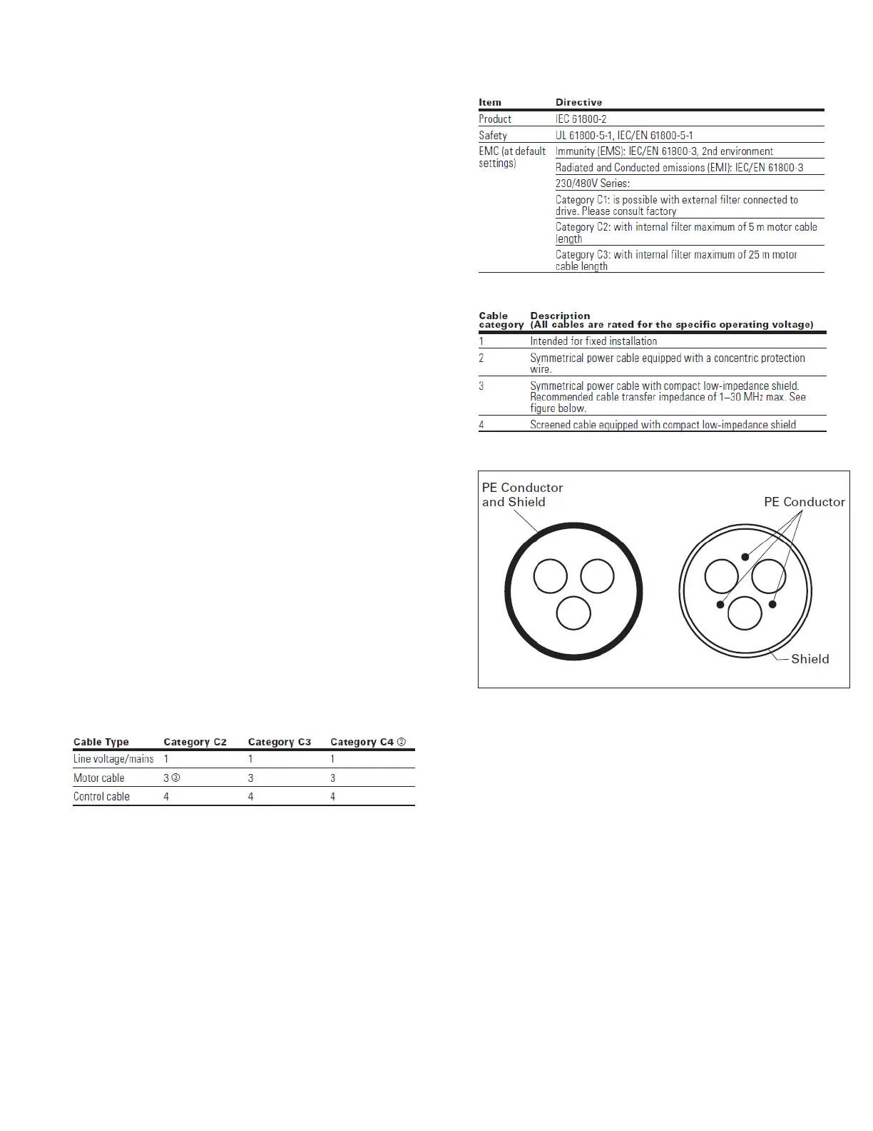
Motor power cable EMC guidelines.
Cable categories
Cable description
 Loading...