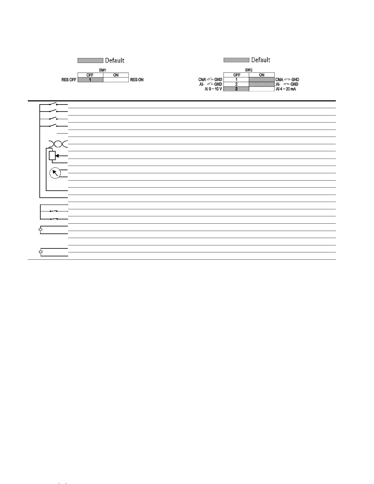
Factory-Set Control Terminal Functions
I/O Connection
Notes:
-
The above wiring demonstrates a SINK configuration. It is important that CMA is wired to ground (as shown by
dashed line). If a SOURCE configuration is desired, wire 24 V to CMA and close the inputs to ground. When
using the +10 V for AI1, it is important to wire AI1- to ground (as shown by dashed line).
-
AI1+ support 10 K potentiometer.
External wiring Terminal Short name Name Default setting Description
Res
1
8
9
DI1 Digital input 1 Run forward Starts the motor in the forward direction.
2
DI2 Digital input 2 Run reverse Start the motor in the reverse direction.
3
DI3 Digital input 3 External fault Triggers a fault in the drive.
4
DI4 Digital input 4 Fault reset Resets active faults in the drive.
5
CMA DI1 to DI4 common Grounded Allows for sourced input.
6
A RS-485 signal A — Fieldbus communication (Modbus RTU, BACNet).
7
B RS-485 signal B — Fieldbus communication (Modbus RTU, BACNet).
AI1+
Analog input 1 0 - 10 V Voltage speed reference (programmable to 4 mA to 20 mA).
AI1- Analog input 1 ground — Analog input 1 common (ground).
10
GND I/O signal ground — I/O ground for reference and control.
11
AO1+ Analog output 1 Output frequency Shows output frequency to motor 0 - 60 Hz (4 mA to 20 mA).
12
GND I/O signal ground — I/O ground for reference and control.
13
10 V 10 Vdc reference output 10.3 Vdc +/- 3% 10 Vdc reference voltage.
14
24 V 24 Vdc control output 24 Vdc In/Out Control voltage input/output (100 mA max.).
15
STO_com Safe torque common — Safe torque Off common.
16
STO2 Safe torque Off 2 — Safe torque Off 2 input.
17
STO1 Safe torque Off 1 — Safe torque Off 1 input.
18
R1NO Relay 1 normally open Run Changes state when the drive is in the run state.
19
R1CM Relay 1 common
20
R1NC Relay 1 normally closed
21 R2NO Relay 2 normally open Fault Changes state when the drive is in the fault state.
22 R2CM Relay 2 common
 Loading...