Procedure
See Figure 3-5 for information on installing the meter (with a weldolet fitting) in a T-piece.
Size the T-piece so that the meter tines are retracted 1 in (25 mm) from the main pipe
wall. For higher flow rates, increase this by 0.39 in (10 mm) for every 1 m/s increase in the
main flow rate.
Important
During installation, always position the meter so that the gap between the tines is vertical.
This position helps prevent the trapping of bubbles or solids on the meter – allowing the
solids to sink and the bubbles to rise. You can use the scribe mark on the spigot (located
between the flange and transmitter) as a reference for the tine orientation. Always orient
the meter so the scribe mark is at either the 12 o’clock or 6 o’clock position.
The gap between the fork tines must always be vertical so that:
• Solids drop down
• Entrained gas will go up
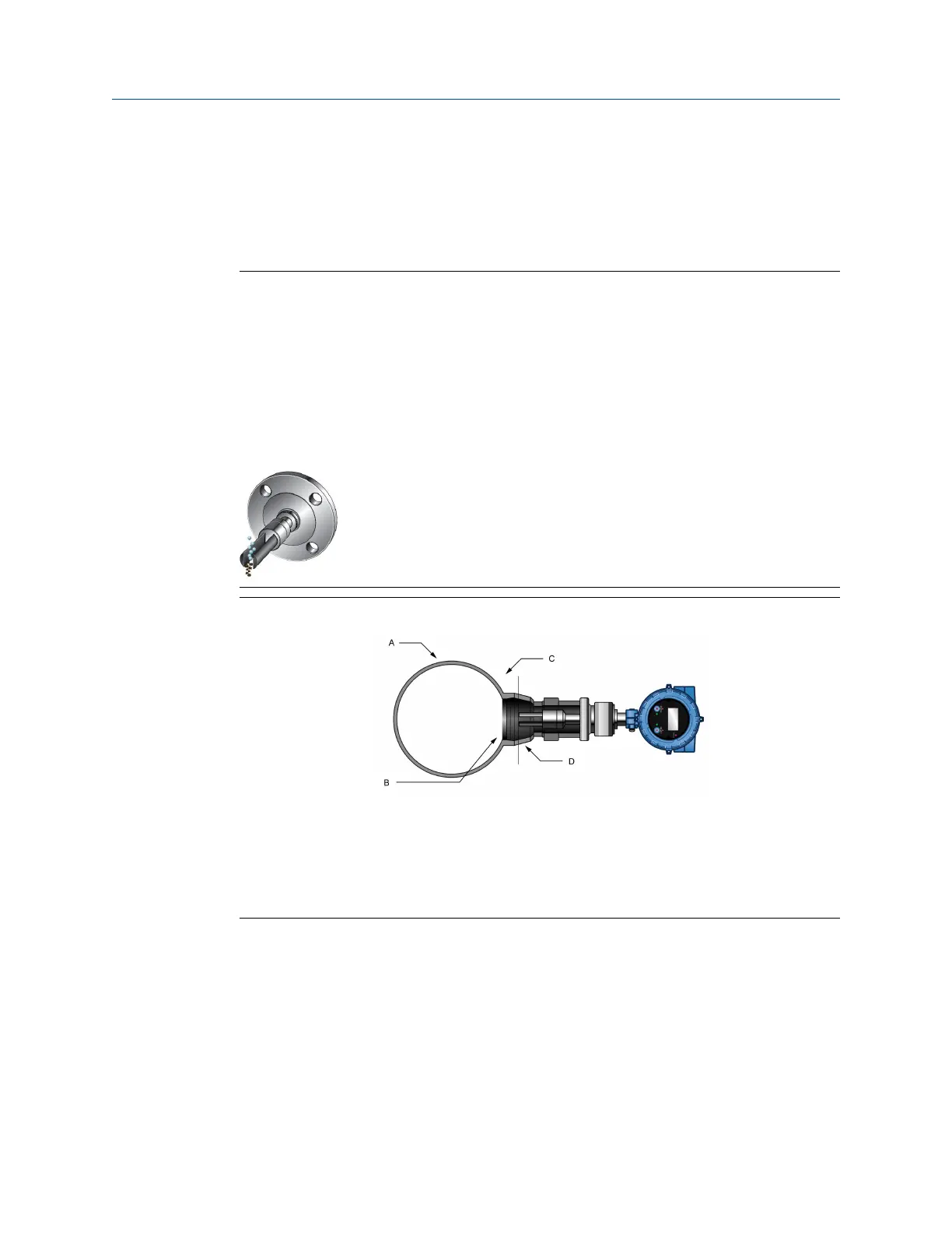
Figure 3-10: T-piece (weldolet fitting) meter installation
A. 4 in (102 mm) pipe or larger for horizontal or vertical installations
B. 2.1 in (53 mm) meter opening in pipeline
C. Distance of meter tines from main pipe wall is determined by the maximum flow rate of
the process
D. Weldolet (purchased to fit pipe diameter)
3.3 Mount with a flow-through chamber
Flow-through chambers are manufactured by Micro Motion, and are available with either
of the following:
• Welded ends or compression fittings that connect into the process pipelines
• 1 in (25 mm), 2 in (51 mm), or 3 in (76 mm) inlet and outlet pipes
Mounting
Installation Manual
May 2019 MMI-20020989
26 Micro Motion Fork Density Meter

 Loading...