3.8 Rotate the display on the transmitter
(optional)
The display on the transmitter electronics module can be rotated 90° or 180° from the
original position.
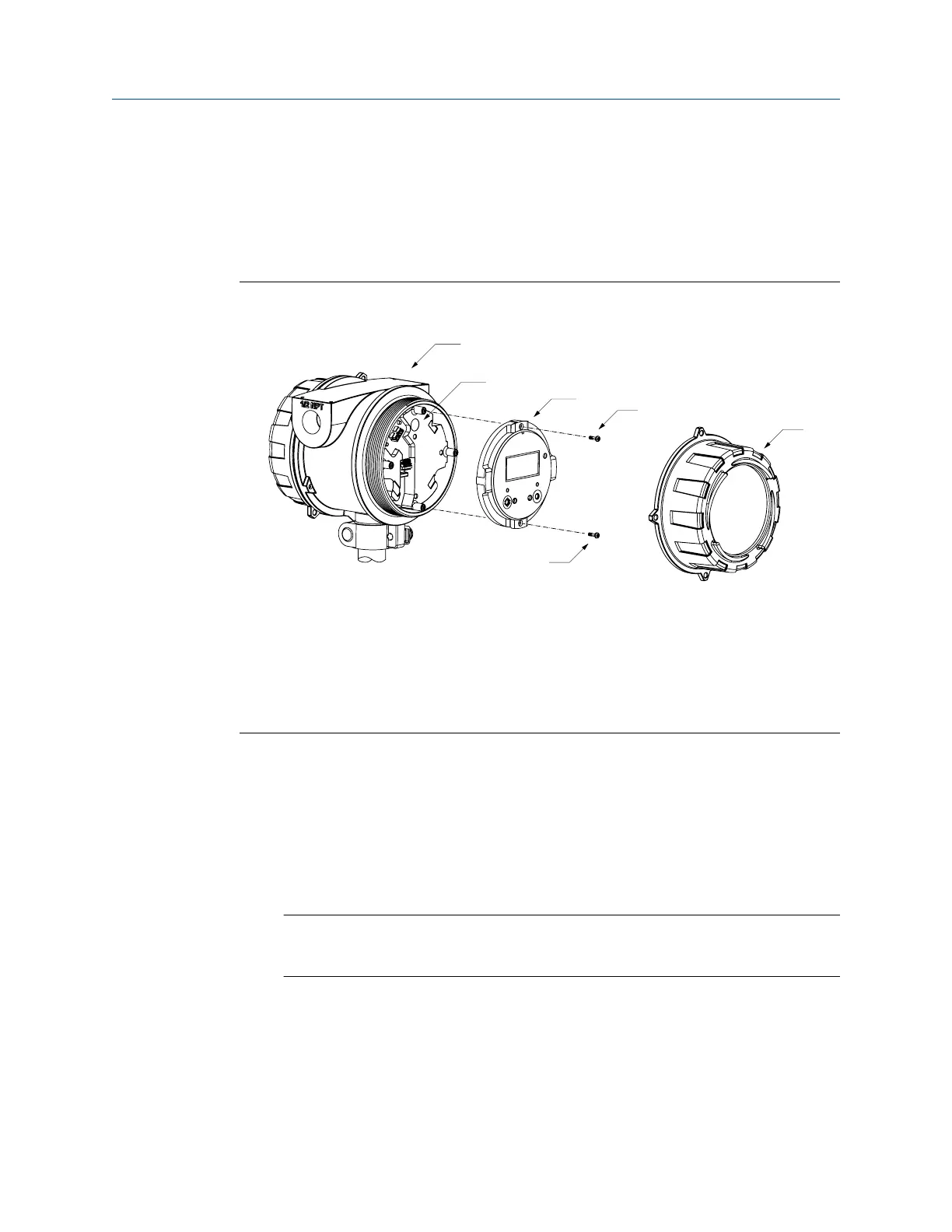
Figure 3-27: Display components
A. Transmitter housing
B. Sub-bezel
C. Display module
D. Display screws
E. Display cover
Procedure
1. If the meter is powered up, power it down.
2. Turn the display cover counterclockwise to remove it from the main enclosure.
3. Carefully loosen (and remove if necessary) the semi-captive display screws while
holding the display module in place.
4. Carefully pull the display module out of the main enclosure until the sub-bezel pin
terminals are disengaged from the display module.
Note
If the display pins come out of the board stack with the display module, remove the
pins and reinstall them.
5. Rotate the display module to the desired position.
6. Insert the sub-bezel pin terminals into the display module pin holes to secure the
display in its new position.
7. If you have removed the display screws, line them up with the matching holes on
the sub-bezel, then reinsert and tighten them.
Installation Manual
Mounting
MMI-20020989 May 2019
Installation Manual 37

 Loading...