□
Verify that the local ambient and process temperatures are within the limits of the
LNG meters.
□
Verify that you are using low-voltage DC power for the core processor. Excess
voltage can damage the core processor.
□
For I.S. applications, refer to Micro Motion ATEX, UL, or CSA installation instructions.
□
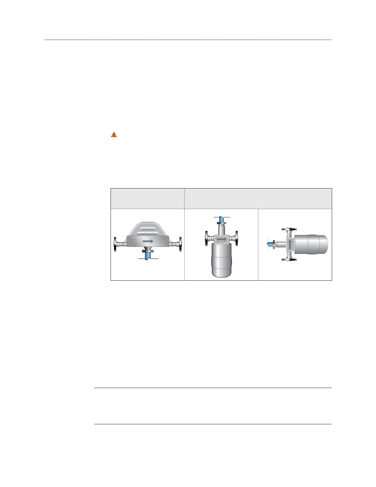
Mount the LNG electronics in any orientation as long as the conduit openings do not
point upward.
CAUTION!
Upward-facing conduit openings risk condensation entering the housing that can
damage the electronics.
□
Install the sensors so that the flow direction arrow on the case matches the actual
forward flow of the process. (Flow direction is also software-selectable.)
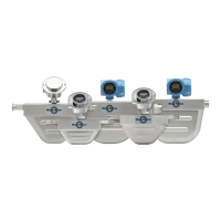
LNGS06
Gas return sensor
LNGM10
Filling sensor
1.3 Power requirements
•
18 to 30 VDC, 3 watts typical, 5 watts maximum
• Minimum 28 VDC with 300 meters of 1 mm
2
power-supply cable
• At startup, power source must provide a minimum of 0.5 amperes of short term
current at a minimum of 18 volts at the electrical parts power input terminals
• The maximum steady state current is 0.2A
• Complies with Installation (Overvoltage) Category II, Pollution Degree 2
Note
• Power requirements assume a single core processor per cable.
• Length and conductor diameter of the power cable must be sized to provide 18 VDC
minimum at the power terminals, at a load current of 0.2 amps.
Planning
2 Micro Motion Liquified Natural Gas Meter

 Loading...