Battery & Energy Pack Manual Chapter 3
GFK-2741J Oct 2019
Energy Packs 23
3.2.4 Hardware Installation
The Energy Pack can be mounted on a standard EN50022 DIN rail or an equipment panel. It
is designed to be mounted adjacent to the Controller and connected to the Controller using
the provided 12” (0.3m) cable (ICRXIACCCBL01A) or a user-supplied cable.
Refer to section on Grounding for important grounding instructions.
Mounting the Energy Pack on a DIN Rail
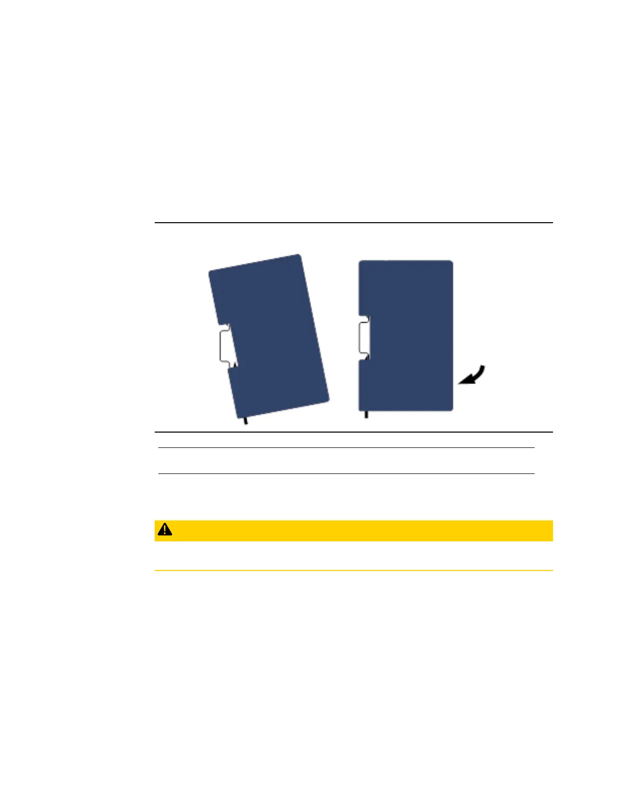
The Energy Pack snaps easily onto the DIN rail. No tools are required.
Figure 7: Mount Energy Pack on DIN Rail
Note: To remove the Energy Pack from the DIN rail, use a small flat-blade screwdriver to pull
down on the tab on the bottom of the Energy Pack and then lift the module off the DIN rail.
Mounting the Energy Pack Directly on a Panel
CAUTION
Over tightening the mounting screws could crack the plastic housing.
Heat dissipation: When mounting the Energy Pack on a panel, allow a minimum clearance
of 25.4mm (1”) on the four sides of the unit (right, left, top and the bottom).
Recommended fasteners: Four M4-0.7 machine screws with minimum length of 25mm (or
8 32, 1” min. length) and nuts.
1.
Drill four mounting holes using the spacing shown in the following drawing.
2.
Use the machine screws and nuts to attach the Energy Pack to the panel.

 Loading...


