Battery & Energy Pack Manual Chapter 3
GFK-2741J Oct 2019
Energy Packs 26
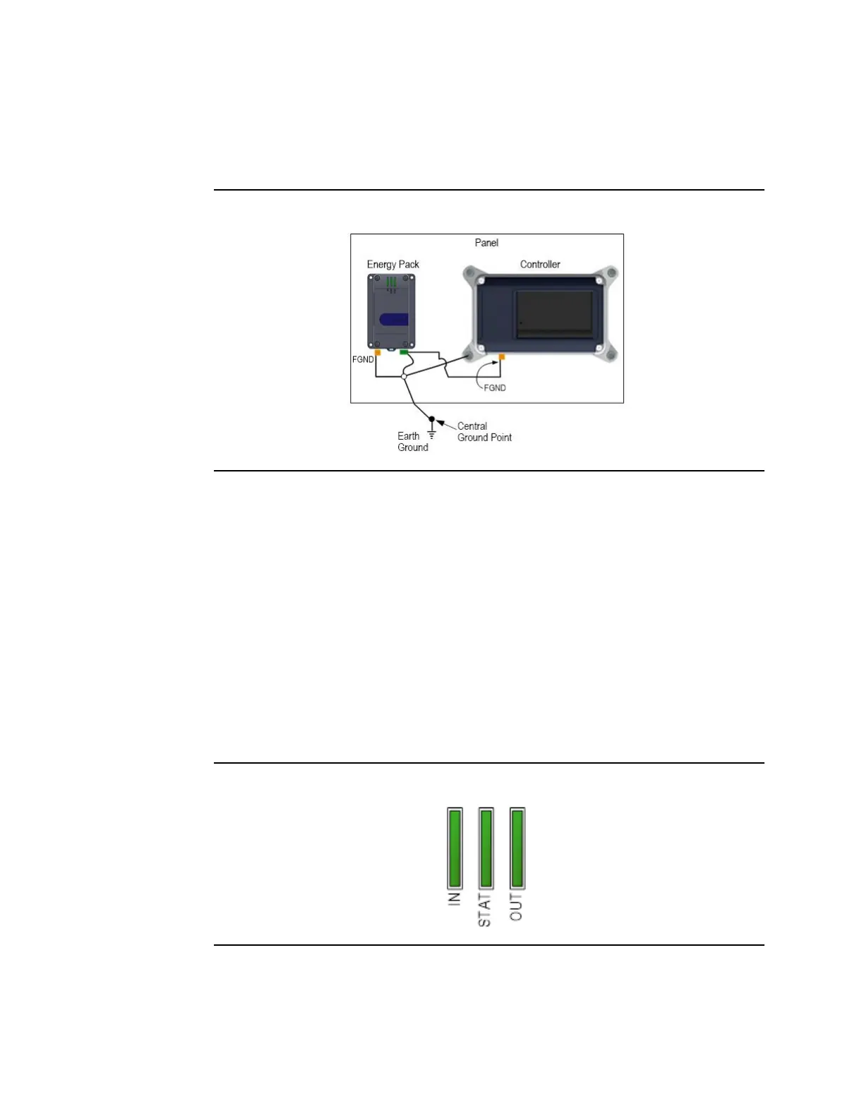
3.2.6 Grounding
Proper grounding of this device is essential. All ground wires must be as short as possible
and terminate at the same grounding point.
Figure 11: Grounding Connections (Example)
3.2.7 Power-Up
When power is applied to the Energy Pack, the power-up process goes through the
following steps:
1.
The IN LED turns on green.
2.
The Energy Pack performs a self-diagnostic test. If this test passes, output power to
the Controller is turned on and the OUT LED turns on green.
3.
Charging of the Cap Pack begins and the STAT LED blinks green.
4.
When charging of the Cap Pack is complete, the STAT LED turns on solid green and
the Energy Pack signals to the controller that it can start run time operation. The
Controller will not start running its application until the Energy Pack signals that it is
fully charged.
Figure 12: LEDs on Energy Pack

 Loading...


