Home
Environnement
Monitor
MP101M
Environnement MP101M User Manual
5
of 1
of 1 rating
196 pages
Give review
Manual
Specs
To Next Page
To Next Page
To Previous Page
To Previous Page
Loading...
Duplication prohibited
MP101M
Environnement
S.A
5–1
SEPTEMBER 2013
CHAPTER 5
CORRECTIVE MAINTENANCE
5.1.
LIST OF FAULTS AND CORRECTIVE ACTIONS
5–4
5.2.
MODULE BOARD OF MP101M
5–8
5.3.
GENERAL CONNECTION DIAGRAM
5–9
Table 5–1 – List of faults and correctives actions
5–4
Table 5–2 – Configuration of Module board
5–8
154
156
Table of Contents
Default Chapter
3
Table of Contents
3
Chapter 0 Safety Guidelines
9
Warning
9
Reminder of Principal Statutory Technical Precautions
10
Presentation of Equipment
11
Figure 0-1 - Beta Gauge Source Holder
11
Figure 0-2 - Source Dimensions (in MM)
12
Risks Assessments
13
Risk Analyses
14
Radiation Protection Recommendations
15
Figure 0-3 - Radioactive Clover
15
Safety Instructions - Example
16
Figure 0-4 - Signaling Label
16
Technical Controls of Radioprotection
17
End of Life of the Analyzer
17
Chapter 1 General - Characteristics
19
General
19
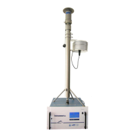
Figure 1-1 - MP101M Presentation
19
Figure 1-2 - Keyboard and Display
19
Figure 1-3 - Front Face with the Door Closed
19
Figure 1-4 - Front Face, Overview of Collector Assembly and Beta Gauge
19
Figure 1-5 - Rear Panel
19
Figure 1-6 - Internal View of the Rear Panel Drawer
19
Figure 1-7 - Components Location
19
Figure 1-8 - Details of the Flow Regulation Part
19
Chapter 2 Principle of Operation
43
Figure 2-1 - General Functional Diagram
43
Figure 2-3 - Flow Regulation Diagram
43
Figure 2-4 - Organisation of Measurements
43
Figure 2-5 - Regulated Sampling Tube (RST) Line Assembly
43
Beta Gauge Principle (Figure 2-1 and Figure 2-2)
45
Flow Regulation Principle
48
Acquisition and Processing of Measurement Parameters
50
Organization of Measurements
50
Regulated Sampling Tube (Rst)
53
Chapter 3 Operation
57
Figure 3-1 - Fluids and Electric Connection
58
Figure 3-3 - Reference Gauge Insertion
58
Figure 3-4 - Putting in Place the Reference Gauge
58
Figure 3-5 - USB Disk
58
Initial Start-Up
60
Programming the Mp101M
63
Description of the Different Screens
66
Chapter 4 Preventive Maintenance
123
Safety Instructions
123
Maintenance Calendar
123
Maintenance Operation Sheets
123
Equipment Necessary for Maintenance
123
Figure 4-1 - Diagram of the Picolino Pump
123
Figure 4-2 - Diagram of the KNF Pump
123
Figure 4-3 - Cleaning of the Sampling Heads PM10 EN12341 and PM2.5 EN14907
123
Figure 4-4 - Cleaning of the US-EPA Standardized PM10 Inlet
123
Figure 4-5 - Cleaning of the US-EPA Standardized VSCC
123
Figure 2-2 - Beta Gauge
152
Chapter 5 Corrective Maintenance
155
5.3. General Connection Diagram
155
List of Faults and Corrective Actions
158
Module Board of Mp101M
162
5
Based on 1 rating
Ask a question
Give review
Questions and Answers:
Need help?
Do you have a question about the Environnement MP101M and is the answer not in the manual?
Ask a question
Environnement MP101M Specifications
General
Brand
Environnement
Model
MP101M
Category
Monitor
Language
English
 Loading...