Duplication prohibited MP101M Environnement S.A
1–1
SEPTEMBER 2013
CHAPTER 1
GENERAL – CHARACTERISTICS
1.1. GENERAL 1–3
1.1.1. PRESENTATION (FIGURE 1–1) 1–3
1.1.2. DESCRIPTION 1–4
1.1.2.1. Front face 1–4
1.1.2.2. Rear panel 1–8
1.1.2.3. Components location 1–10
1.1.3. ASSOCIATED EQUIPMENT 1–12
1.1.3.1. Sampling assembly 1–12
1.2. CHARACTERISTICS 1–13
1.2.1. TECHNICAL CHARACTERISTICS 1–13
1.2.2. OPERATING CHARACTERISTICS 1–15
1.2.3. STORAGE CHARACTERISTICS 1–15
1.2.4. INSTALLATION CHARACTERISTICS 1–16
1.2.4.1. Composition 1–16
1.2.4.2. Installation 1–17
1.2.4.3. Links between units (Figure 1–11) 1–21
1.2.4.4. Dimension and weight (Figure 1–12) 1–21
1.2.4.5. Handling and storage 1–21
1.2.5. CERTIFICATIONS 1–23
1.2.5.1. PM
10
USEPA designation 1–23
1.2.5.2. PM
2.5
USEPA designation 1–23
1.2.5.3. EN12341 designation 1–24
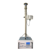
Figure 1–1 – MP101M presentation 1–2
Figure 1–2 – Keyboard and display 1–4
Figure 1–3 – Front face with the door closed 1–5
Figure 1–4 – Front face, overview of collector assembly and beta gauge 1–7
Figure 1–5 – Rear panel 1–8
Figure 1–6 – Internal view of the rear panel drawer 1–9
Figure 1–7 – Components location 1–10
Figure 1–8 – Details of the flow regulation part 1–11
Figure 1–9 – Installing the regulated sampling tube (RST) 1–18
Figure 1–10 – Regulated sampling tube (RST) 1–19
Figure 1–11 – Links between units 1–21
Figure 1–12 – Outline dimensions 1–22
 Loading...