Confidential
Adjustment Details of Adjustments 71
Epson WF-5690/4640/4630/5620/5190/5110 series Revision D
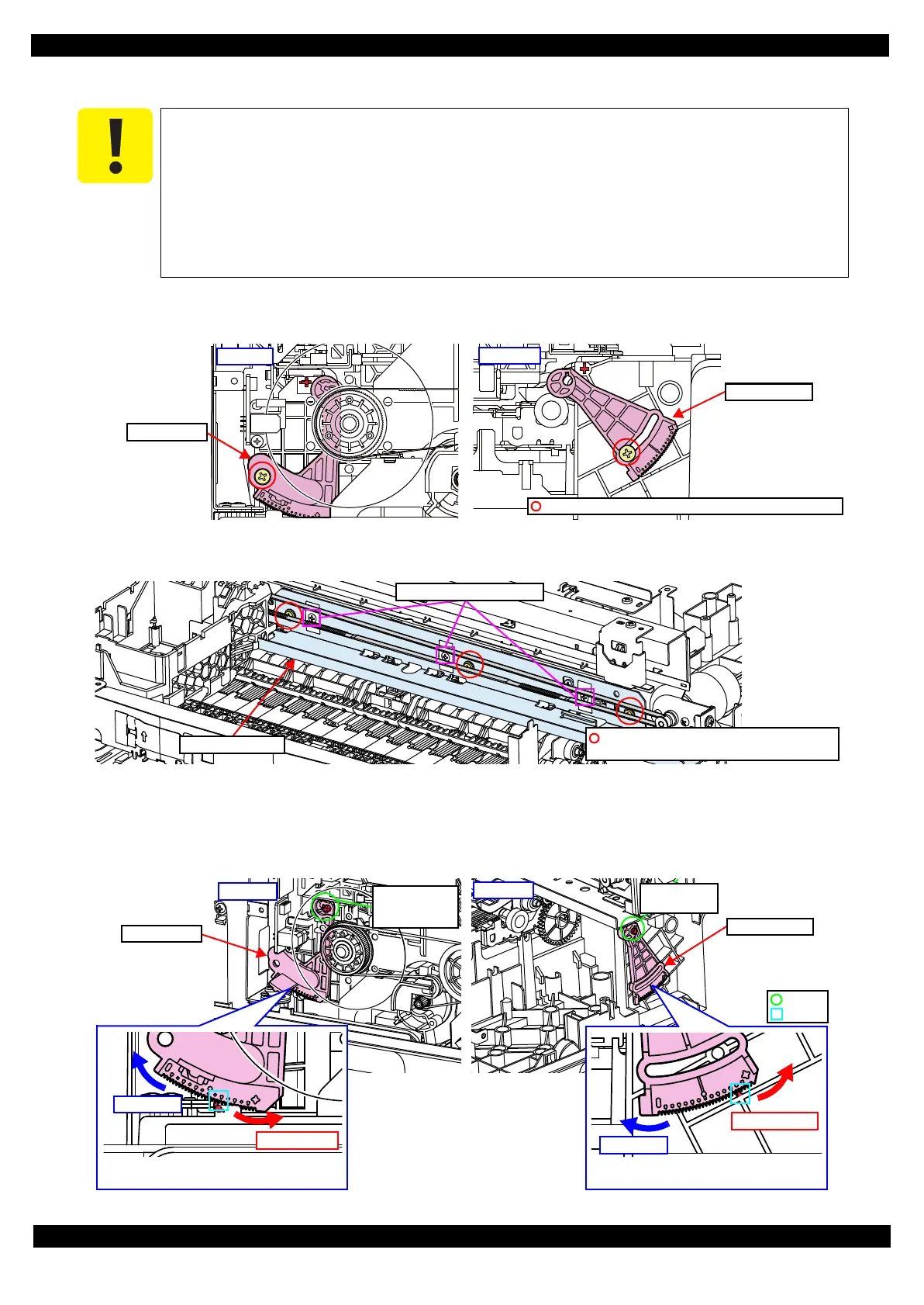
3.2.4.2 PG Adjustment procedure
1. Remove the screws (one each) that secure the PG Cam Left and PG Cam Right on both sides of the printer,
and remove the PG Cam Left and PG Cam Right.
Figure 3-21. PG Cam Left/PG Cam Right
2. Loosen the screws (x3) that secure the CR Guide Frame.
Figure 3-22. CR Guide Frame
3. Set the PG Cam Left to the dowel of the Paper Guide Front Assy, and set the PG Cam Right to the dowel of
the Frame Base.
4. Align the “+” marked notches of the PG Cams with the ribs of the Frame Base so as to make the PG the widest.
Figure 3-23. Installing the PG Cam Left/PG Cam Right
When performing the PG adjustment, make sure of the following.
perform the PG adjustment with the new cartridges installed on the CR Unit before
installing the CR Scale.
Move the CR Unit by pulling the top pf the CR timing belt.
Be careful not no damage the nozzle surface of the Printhead with the thickness gauge.
When make the Printhead touch the thickness gauge, be careful not to let the Printhead
un onto the gauge.
C.B.P-TITE (P2) SCREW 3x10-F/ZN-3C (6 ± 1kgf·cm)
PG Cam Left
PG Cam Right
C.B. SCREW 3 x 6 F/ZN-3C (8 ± 1kgf·cm)
P.W. 3 x 0.5 x 8 F/ZN-3C
Do not loosen these screws.
CR Guide Frame
Right side
Dowel of
Frame Base
Left side
Dowel of Paper
Guide Front
Assy
Rib
Dowel
Align “+” (notch for the widest PG) on the
PG Cam with the rib.
Align “+” (notch for the widest PG) on the
PG Cam with the rib.
PG Cam Left
PG Cam Right
 Loading...