Confidential
Disassembly/Reassembly Disassembly/Reassembly Procedures 31
Epson WF-7620/7610/7110 Series Revision B
2.2.3 Disassembly Flowchart
This section describes procedures for disassembling the parts/units in a flowchart format. For some parts/units,
detailed procedures or precautions are provided (accordingly indicated by icons and cell's color). Refer to the
explanations in the example chart below and perform an appropriate disassembling and assembling procedure.
(See "2.3 Detailed Disassembly/Reassembly Procedure for each Part/Unit (p38)".)
For routing cables, see "2.4 Routing FFCs/cables (p47)".
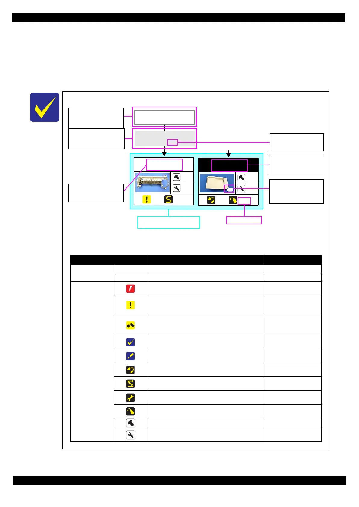
The example below shows how to see the charts on the following pages.
Item Description Reference
Parts/unit name
White-letter
Part/unit supplied as an ASP ---
Black-letter
Part/unit not supplied as an ASP ---
Icon
Indicates a practice or condition that could result in
injury or loss of life if not strictly observed.
Indicates the reference
page in blue-letter
Indicates a practice or condition that could result in
damage to, or destruction of equipment if not strictly
observed.
Indicates the reference
page in blue-letter
Indicates the parts that are inevitably broken in the
disassembling procedure, and should be replaced with a
new one for reassembly.
---
Indicates necessary check items in the disassembling/
assembling procedure.
Indicates the reference
page in blue-letter
Indicates supplementary explanation for disassembly is
given.
Indicates the reference
page in blue-letter
Indicates particular tasks to keep quality of the units are
required.
Indicates the reference
page in blue-letter
Indicates particular routing of cables is required.
Indicates the reference
page in blue-letter
Indicates particular adjustment(s) is/are required.
Chapter 3 " Adjustment
(p52)"
Indicates lubrication is required.
Chapter 4 " Maintenance
(p75)"
Indicates the number of screws securing the parts/units. ---
Indicates the points secured with other than a screw
such as a hook, rib, dowel or the like.
---
USB Cover
1
4
(p 22) (p 43)
S2
Main Frame Unit
---
---
(p 21) (p 27)
Paper Guide
Upper Assy (p29)
CR Timing Belt
FFC/Cable * 1
Note "*": The boxes with only part names indicates the removal of such parts. If the names of FFCs or cables are
shown, disconnect the FFCs or cables from their connectors.
Black letters indicate a
part/unit not supplied as
an ASP.
The name enclosed in gray
indicate a part/unit that
must be removed on the
way to the target parts.
Shows necessary
procedures before
removing the following
parts.*
Shows the procedure
number on the “FFC/
cable list”.
White letters indicate a
part/unit supplied as
an ASP.
Shows the screw types
and the specified
torque in the “Screw
type/torque list”.
Shows removal/installation
as a unit/assy. is available.
Reference page
 Loading...