Epson WF-7620/WF-7610/WF-7110 Series Revision B
Confidential
Disassembly/Reassembly 32
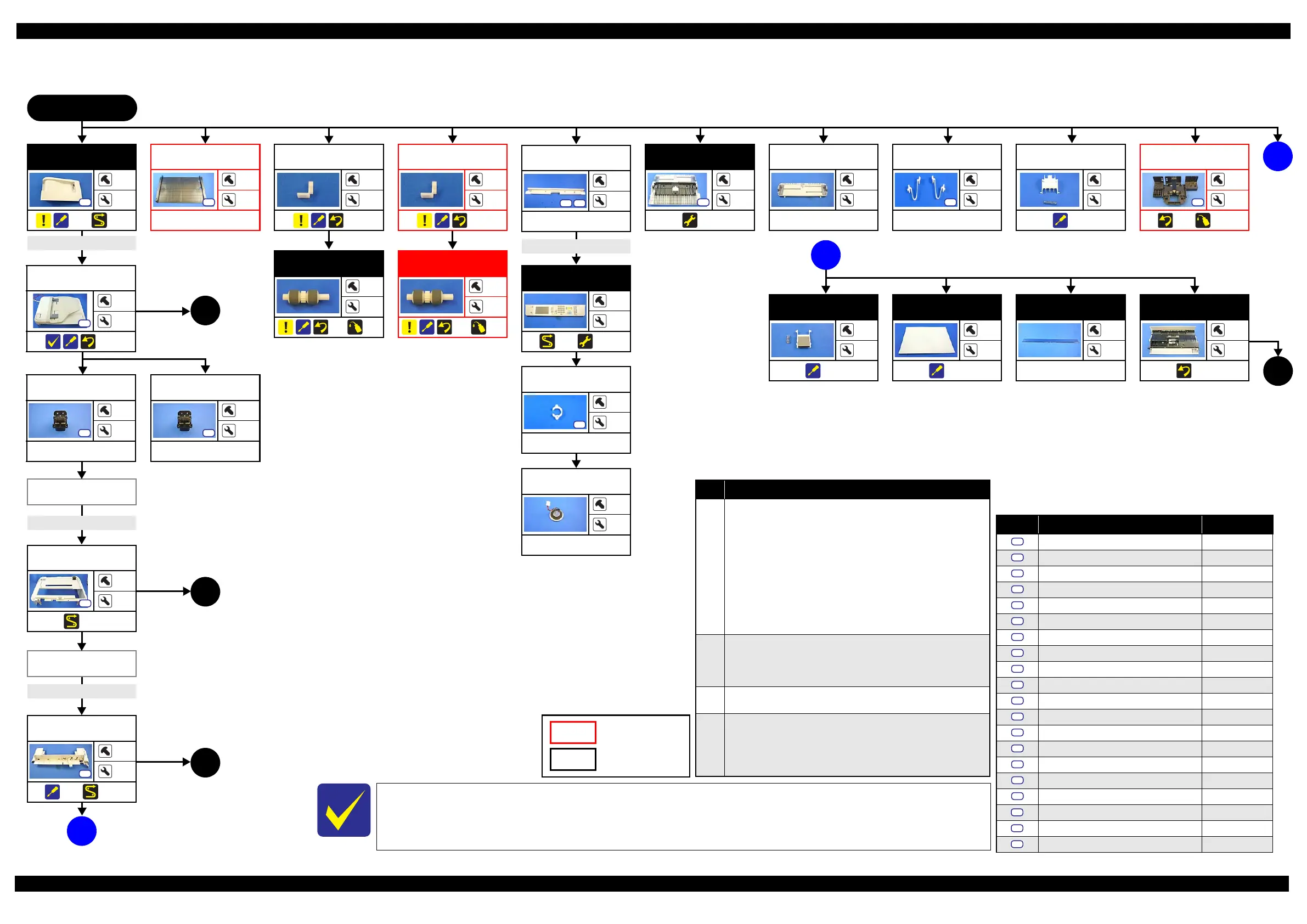
2.2.3.1 Housing Part (WF-7620/WF-7610 Series)
Flowchart 2-1. Disassembly Flowchart of Housing Part (1)
With WF-7620/WF-7610 Series, some parts differ depending on the models, so the disassembly procedures in this
flowchart differ. For the details, see "2.2.2Functional differences between models and component parts
(p30)" and refer to the flowchart.
See"2.2.3.3Printer Mechanism Part (p34)" for disassembly of the Housing Part of WF-7110.
START
B
USB Cover
2
7
(p 41) (p 48)
Duplex Unit
Cover
2
4
(p 52)
S5
3
(p 34)
(p 36)
(p 36)
Specific parts/unit
Common parts/unit
MSF Unit
---
2
---
Pickup Holder
2nd
---
1
(p 41)
MSF Stopper
Belt
4
4
---
Paper Stopper
Assy 2nd
2
---
(p 41)
(p 75)
Pickup Roller 1st
---
---
(p 41)
(p 75)
Housing Front
Assy
2
2
(p 41) (p 48)
A
(p 32)
Screw type/torque list
Symbol
Screw Type Torque
C.B.P-TITE SCREW 2.5x8 F/ZN-3C 4 ± 1kgfÅEcm
C.B.P-TITE SCREW 3x10 F/ZN-3C 6 ± 1kgfÅEcm
C.B.P-TITE SCREW 3x10 F/ZN-3C 8
± 1kgfÅEcm
C.B.P-TITE SCREW 3x5 F/ZN-3C 6 ± 1kgfÅEcm
C.B.P-TITE SCREW 3x8 F/ZN-3C 6
± 1kgfÅEcm
C.B.P-TITE(P4) SCREW 3x8 F/ZN-3C 6 ± 1kgfÅEcm
C.B.P-TITE(S-P1) SCREW 3x12 F/ZB-3C 6
± 1kgfÅEcm
C.B.P-TITE(S-P1) SCREW 3x12 F/ZN-3C 6 ± 1kgfÅEcm
C.B.S-TITE SCREW 2.6x6 F/ZN-3C 4
± 1kgfÅEcm
C.B.S-TITE SCREW 3x6 F/ZN-3C 6 ± 1kgfÅEcm
C.B.S-TITE SCREW 3x6 F/ZN-3C 8
± 1kgfÅEcm
C.B.S-TITE(P4) SCREW 3x10 F/ZN-3C 6 ± 1kgfÅEcm
C.B.S-TITE(P4) SCREW 3x8 F/ZN-3C 6
± 1kgfÅEcm
C.C SCREW 3x5 F/ZN-3C 8 ± 1kgfÅEcm
C.P SCREW 3x4 F/ZN-3C 6
± 1kgfÅEcm
C.P-TITE SCREW 2.5x6 F/ZN-3C 3 ± 0.5kgfÅEcm
C.P-TITE SCREW 3x4 F/ZN-3C 3
± 0.5kgfÅEcm
C.B.S-TITE SCREW 3x8 F/ZN-3C 6 ± 1kgfÅEcm
C.B.S-TITE SCREW 3x8 F/ZN-3C 8
± 1kgfÅEcm
C.B.P-TITE SCREW 3x10 F/ZB-3C 6 ± 1kgfÅEcm
S1
S2
S3
S4
S5
S6
S7
S8
S9
S10
S11
S12
S13
S14
S15
S16
S17
Pickup Holder
1st
---
1
(p 41)
Assist Roller
Holder Assy
---
3
(p 41)
Decoration Plate
4
---
---
S2
Lower Case
6
---
---
S2
FFC/Cable* 1
ADF/Scanner
Unit
4
---
(p 38)
S7
Decoration Plate
(p32)
Hinge Right
2
---
---
S2
FFC/Cable* 3
FFC/cable list
No. FFC/Cable
1
Disconnect the following FFC and cables from the connectors on the
Main Board, and release their routing.
• ADF motor cable (CN33)
• ADF PE sensor cable (CN71)
• ADF document sensor cable (CN72)
• ADF encoder sensor cable (CN73)
• Paper Support Encoder Sensor cable (CN76)
• ADF plunger cable (CN77)
• Scanner Motor cable (CN32)
• Scanner FFC (CN70)
• Scanner Open Sensor cable (CN74)
2
Disconnect the FFCs/Cables.
• Panel FFC (CN20)
• Speaker cable
Disconnect the Panel Grounding Wire (S02).
3
Disconnect the Duplex Unit Cover Open Sensor cable from the
connector (CN60) on the Main Board, and release the routing.
4
Disconnect the following FFC and cable from the connectors on the
Main Board.
• Panel FFC (CN20)
• Cover Open Sensor cable (CN53)
Disconnect the Panel Grounding Wire (S11).
Panel Unit (p32)
Panel Unit
---
---
(p 48)
(p 52)
FFC/Cable* 4
Pickup Roller 2nd
---
---
(p 41)
(p 75)
FFC/Cable* 2
Speaker Cover
2
---
---
Speaker
---
---
---
(p 32)
(p 36)
4
ADF Cover Assy
---
2
(p 38)
MSF Cover
---
3
---
Document Pad
---
---
(p 40)
ADF Pad Assy
---
4
(p 39)
(p 36)
2
1
Hinge Left
2
---
---
S2
Housing Upper
Assy
4
---
(p 47)
A
 Loading...