XT Series DISK RECORDER - Technical Reference
EVS Broadcast Equipment SA - Nov 2005
Issue 3.0
18
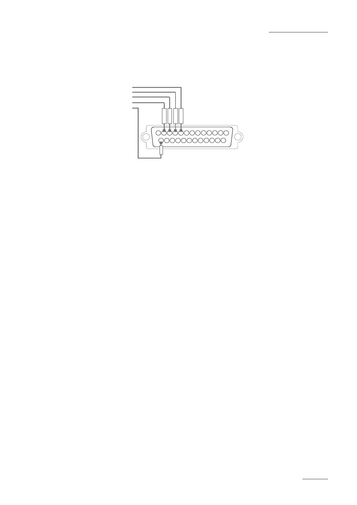
3.5.3 TTL Æ TTL INPUTS ON THE XT SERVER (GPI INPUTS 5, 6, 7,
8)
12
3
4
5678910
11
12
13
141516171819202122232425
I
N
+
G
P
I
4
G
r
o
u
n
d
I
N
+
G
P
I
3
I
N
+
G
P
I
2
I
N
+
G
P
I
1
I
N
+
G
P
I
7
I
N
+
G
P
I
6
I
N
+
G
P
I
5
TTL 1
TTL 2
TTL 3
TTL 4
Common Ground
I
N
+
G
P
I
8
Each TTL input on the DB25 is directly connected to the pin of the TTL
connector on the device triggering the GPI. The ground must be common
between the DB25 connector of the XT and the external device.
3.5.4 MTPC GPIO CONNECTOR 15/10/02
GPIO Connector: SUB-D 25-pins Male
1 Relay 3 14 Relay 3
2 Relay 2 15 Relay 2
3 Relay 1 16 Relay 1
4 Relay 0 17 Relay 0
5 IN+ opto 3 18 IN- opto 3
6 IN+ opto 2 19 IN- opto 2
7 IN+ opto 1 20 IN- opto 1
8 IN+ opto 0 21 IN- opto 0
9 I/O TTL 3 22 GND (Return I/O 3)
10 I/O TTL 2 23 GND (Return I/O 2)
11 I/O TTL 1 24 GND (Return I/O 1)
12 I/O TTL 0 25 GND (Return I/O 0)
13 + 5V 50mA max.
GPIO hardware specification:
4 X Relay isolated output:
• normally open contact (power off -> open)
• maximum 1A
• maximum 50 Volts
• typical life time: 100.000.000 switching
4 X Opto isolated input:
• The input consists in an opto diode (VF @ 1.1 Volt) in series with a
470 ohm resistor).
• Typical switching point @ 1.4 mA, for secure operation:
 Loading...

![Preview: EVS XT[2]](https://data.easymanua.ls/products/617905/200x200/evs-xt-2.webp)


