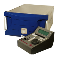
XT Series DISK RECORDER - Technical Reference
EVS Broadcast Equipment SA - Nov 2005
Issue 3.0
38
4.2.5.1 JUMPERS ON THE COHX BASE MODULE
ST1, ST2 : these 2 jumpers must be installed on the last COHX board of
the server (i.e. on COHX #1, 2 or 3 if there are respectively 1, 2 or 3
COHX board installed in the server)
ST3 (SPARE) : « parking » for jumpers for ST1 and ST2 when these are
not used
ST4 (only on COHX with genlock) : must be set to HiZ (or not installed).
Note that the Genlock Loop connector on the back panel of the XT[2]
server must always
be terminated with a 75 Ohm load if it is not used.
ST5 : defines the position of the board inside the server. Must be set to
« 1 » for a COHX with genlock, and to « 2 » or « 3 » for a COHX board
without genlock, depending on its position in the server.
4.2.5.2 LEDS ON THE COHX BASE MODULE WITH GENLOCK
GLK :
Off when the genlock module is not initialized.
Blinks green when the genlock module is properly initialized, but not valid
genlock signal is detected.
On, steady green when the module is initialized and a valid genlock signal
is detected.
Red (steady or intermittent) : genlock problem. The led lights red every
time a resync is needed.
PSU OK :
On (green) when all voltages are present and in the allowed range,
otherwise the led is off.
4.2.5.3 LEDS ON THE COD A AND COD B MODULES (FROM LEFT TO
RIGHT)
CPU : blinks (green) to indicate CPU activity. If this led is permanently on
(green) or off, it means there is a problem with the processor of the COD
module.
PLAY : on (green) when the COD module is set by the software in play
mode. Off when it is set in record mode.
PVID : on (green) when a valid video signal has been detected on the J8
connector (SD/HD SDI input), whether the COD module is in play or record
mode.
TF (transfer) : flashes green while data transfers occur between the COD
module and the HCT-X board.
M1, M2, M3, M4 : not yet used.

