XT Series DISK RECORDER - Technical Reference
EVS Broadcast Equipment SA - Nov 2005
Issue 3.0
29
4.2.1.1 LED’S INFORMATION:
Bus_A/C/D/E: shows whether the video input A is sent to bus A or C
and the video input B is sent to bus D or E
PVID_ A/B: shows the video signal is present on input A/B
USER:
LOCK: shows the unit is actually locked
on the Reference signal.
PGLCK: shows the presence of the reference signal
-12V, +5V, +12V: show all voltages are OK.
4.2.1.2 CONNECTORS:
IN_A/B: Serial Digital video inputs
LOOP_A/B: Loop through (CVBS or SDI) of digital input A/B
for E/E monitoring
REF_OUT: Genlock output
MON_A/B: Optional: Serial digital monitoring outputs (requires
chips U79 and U77)
OUT_A/B: Serial Digital video outputs
4.2.1.3 BOARD CONFIGURATION:
4.2.1.3.1 Adding an second and third Digital i/O E board
!
Make sure the system is turned off and mains is disconnected before moving/modifying
any component !
Before adding a second and a third I/OE boards into the LSM-XT chassis,
remove the INTG jumper (ST2) of IRQ A position from the second and third
I/OE boards. But do not remove the INTG jumper from the first I/OE board.
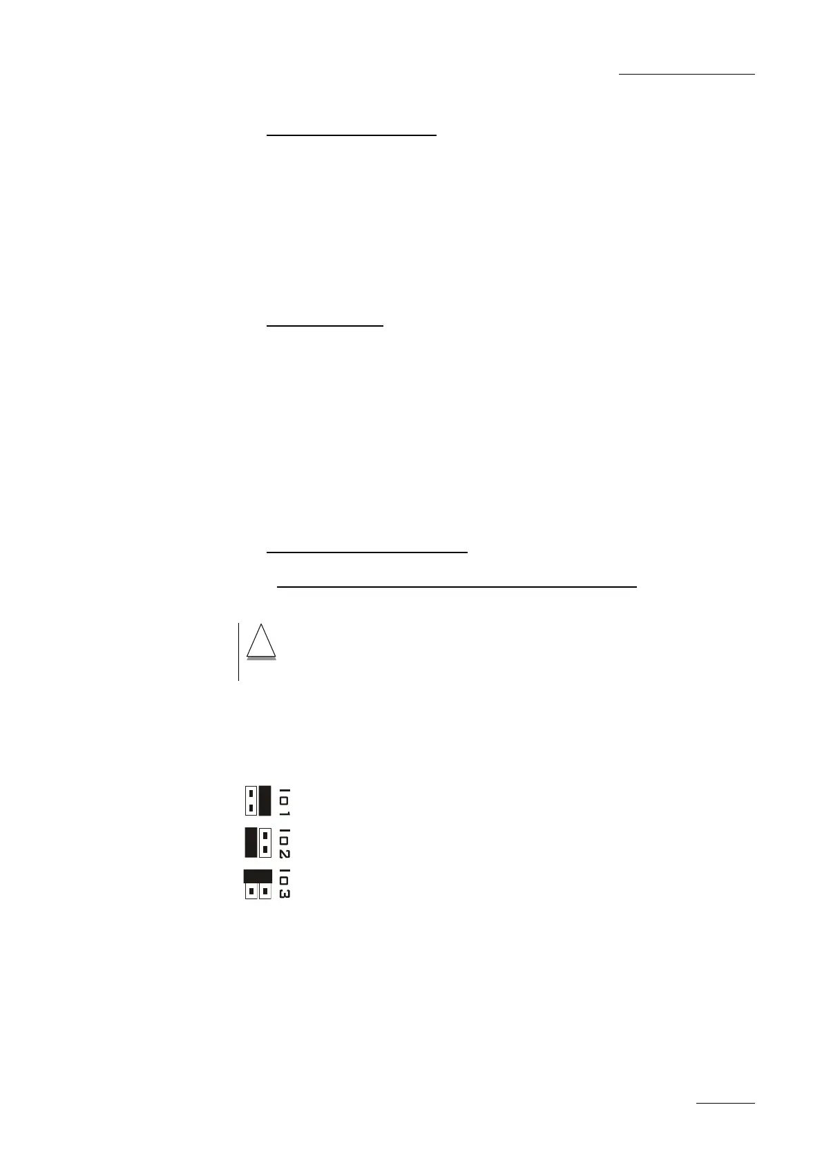
Then refer to this diagram to change jumper position (ST3) on
each I/OE board.
The three digital I/O boards have different jumper configurations
depending on the location inside the mainframe.
 Loading...

![Preview: EVS XT[2]](https://data.easymanua.ls/products/617905/200x200/evs-xt-2.webp)


