XT Series DISK RECORDER - Technical Reference
EVS Broadcast Equipment SA - Nov 2005
Issue 3.0
34
4.2.3.1 LED’S INFORMATION:
-12V, +5V, +12V: show all voltages are OK.
625i 50.00/525i 59.94, 720p 50.00, 720p 59.94, 1080i 50.00, 1080i 59.94:
show the video standard in use.
625i 50.00 /
525i 59.94 Led
720p 50.00 Led
720p 59.94 Led
1080i 50.00 Led 1080i 59.94 Led
625i 50.00Hz ON ON ON
525i 59.94Hz ON ON ON
720p 50.00Hz ON
720p 59.94Hz ON
1080i 50.00Hz ON
1080i 59.94Hz ON
LOCK: shows the unit is actually locked
on the reference signal.
PGLCK: shows the presence of the reference signal
TRI-SYNC shows the unit is locked on the tri-level sync
4.2.3.2 CONNECTORS:
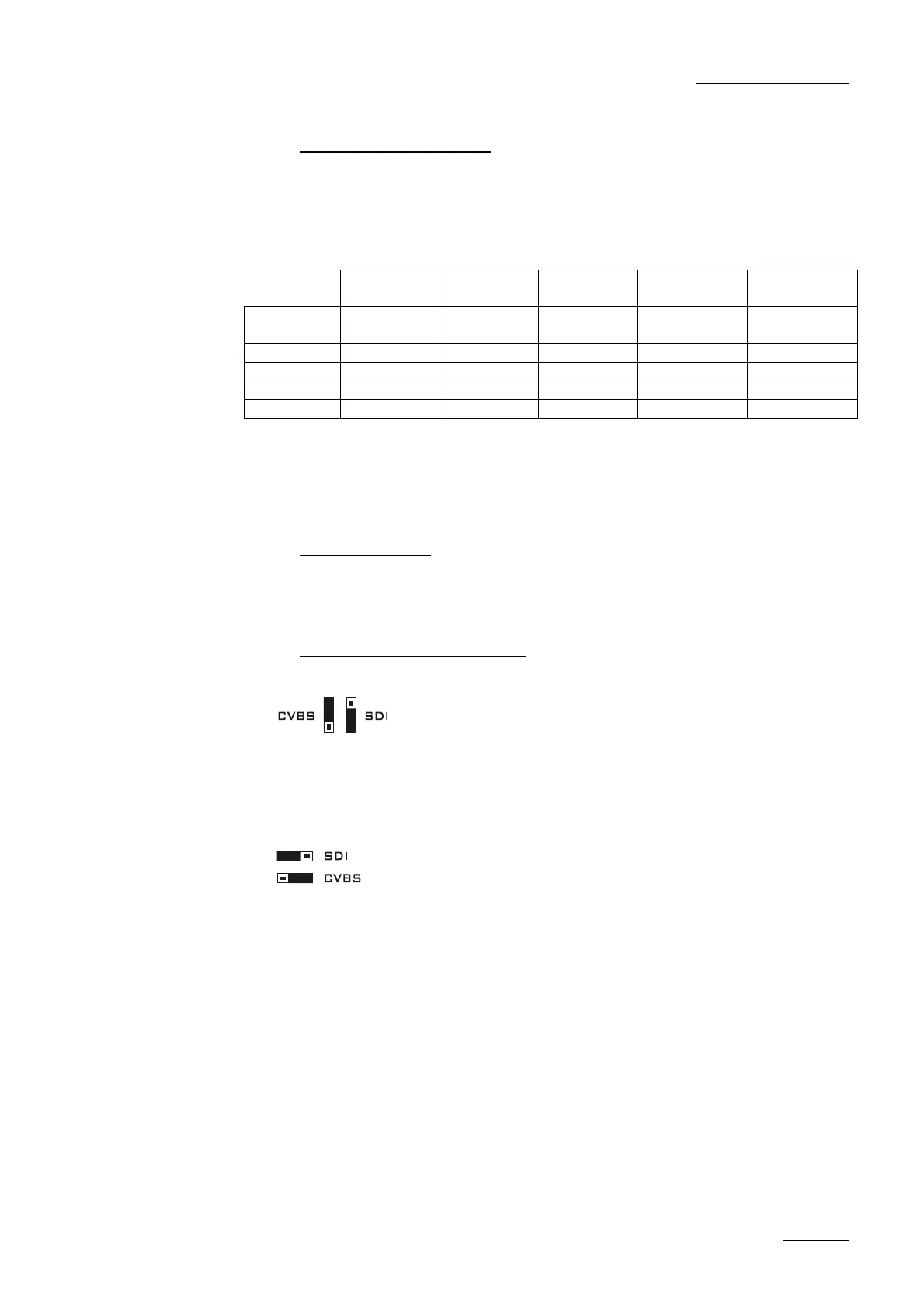
MON_A/B/C/D: SDI or CVBS monitoring outputs. See jumpers’ positions
4.2.3.3 BOARD CONFIGURATION:
Moving the ST2 and ST3 jumpers allows you to select analogue or digital
monitoring from the “Outputs Monitoring” BNC connectors on the rear panel
(down-converted monitoring/clean output of PGM1 and PGM2/PRV).
Moving the ST4, ST5, ST6 and ST7 jumpers allows you to select analogue
or digital monitoring from the “E/E Monitoring” BNC connectors on the rear
panel (down-converted monitoring of inputs 1, 2, 3, 4).
 Loading...

![Preview: EVS XT[2]](https://data.easymanua.ls/products/617905/200x200/evs-xt-2.webp)


