XT Series DISK RECORDER - Technical Reference
EVS Broadcast Equipment SA - Nov 2005
Issue 3.0
43
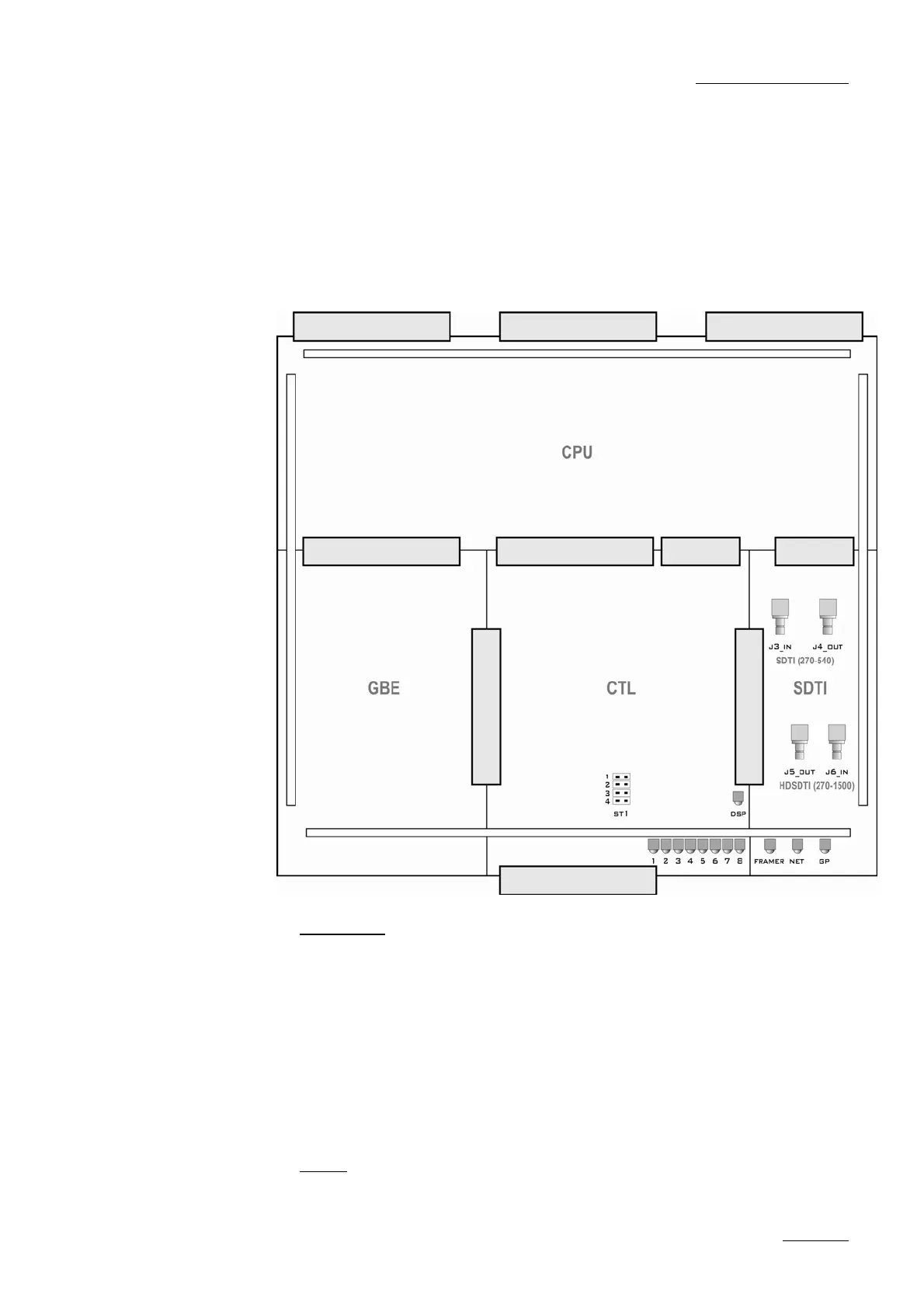
4.4.2 HCTX BOARD
The HCTX board is actually divided in 4 parts (3 in front, 1 in the back).
Front left : spare module, reserved for future Gigabit Ethernet option ;
Front center : controller module ; front right : Xnet[2] module (SDTI) ;
back : CPU module
4.4.2.1 JUMPERS
ST1-1 on controller module (front center) : jumper must be installed on
ST1-1 only when the HCT-X board is used with previous video codec
boards (SD CODEC6, COHD, COHU). This jumper is automatically
detected by the software application, and an error message is generated if
it is not properly set
ST1-2, ST1-3 and ST1-4 on controller module are not used. No jumper
must be installed on these
ST1 on CPU module (rear corner, left) : for EVS internal tests only (used to
reset the board). Never install that jumper, or the board will be in a
permanent reset state !
4.4.2.2 LEDS
Leds on the Xnet[2] module (SDTI), from left to right :
 Loading...

![Preview: EVS XT[2]](https://data.easymanua.ls/products/617905/200x200/evs-xt-2.webp)


