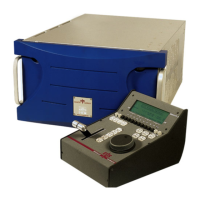
XT Series DISK RECORDER - Technical Reference
EVS Broadcast Equipment SA - Nov 2005
Issue 3.0
44
FRAMER : on (green) when the signal on the Xnet or Xnet[2] IN connector
is a valid EVS SDTI signal.
NET : on (green) when the Xnet SDTI network is actually established (SDTI
loop closed, correct speed, etc)
GP : not used
Leds on the controller module (center), from left to right :
Led 1 : lights red when an error occurs while booting the HCT-X board
Led 2 to 8 : display the boot sequence of the HCT-X board (cfr note below)
DSP led : blinks green to show DSP activity
Note : when booting the HCT-X board, leds 1 to 8 will light according to the following
sequence :
Hardware reset Æ all leds on (1 : red ; 2 to 7 : green)
Setup of CPU basic registers Æ led 2 on (green)
Check of CPU/PC DPRAM
Æ if error : led 1 on (red) + led 8 on (green)
Æ otherwise, led 3 on (green) if check is successful
Polling for PC commands Æ led 4 on (green)
Switching to enhanced mode Æ led 5 on (green)
Executing PC commands until execution requests end Æ led 6 on (green)
Jump to SDRAM and execute microcode
4.4.2.3 CONNECTORS
On the Xnet[2] module (SDTI) :
J3 : IN connector for Xnet (SDTI network 270/540Mbps with relay)
J4 : OUT connector for Xnet (SDTI network 270/540Mbps with relay)
J5 : OUT connector for Xnet[2] (SDTI network 270/540/1485Mbps without
relay)
J6 : IN connector for Xnet[2] (SDTI network 270/540/1485Mbps without
relay)
Note : J3 must
be used with J4, and J5 must be used with J6. Never use J3 with J5 or J4 with
J6 !

 Loading...