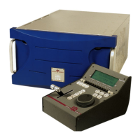
XT Series DISK RECORDER - Technical Reference
EVS Broadcast Equipment SA - Nov 2005
Issue 3.0
2
3.7.2
CODA2............................................................................................................................................................21
3.7.3
CODA3............................................................................................................................................................21
3.7.4
CODA3B.........................................................................................................................................................21
3.7.5
CODA4............................................................................................................................................................22
3.7.6
CODA0............................................................................................................................................................22
3.8
Connecting multiple XT’s on XNet : ...................................................................................................................23
3.8.1
Connection diagram without EVS XHub SDTI HUB.....................................................................................23
3.8.2
Connection diagram witH EVS XHub SDTI HUB.........................................................................................24
3.8.3
Required conditions to set up and run XNet....................................................................................................24
3.8.4
Starting XNet...................................................................................................................................................26
3.8.5
XNet Performances & Troubleshooting..........................................................................................................26
4 HARDWARE DESCRIPTION........................................................................................27
4.1
Boards and Slot Configurations...........................................................................................................................27
4.1.1
6U Frame.........................................................................................................................................................27
4.1.2
4U Frame.........................................................................................................................................................27
4.2
Video and Reference Boards ................................................................................................................................28
4.2.1
Digital I/O E....................................................................................................................................................28
4.2.1.1
LED’s Information:.....................................................................................................................................29
4.2.1.2
Connectors:..................................................................................................................................................29
4.2.1.3
Board configuration:....................................................................................................................................29
4.2.1.3.1
Adding an second and third Digital i/O E board ..................................................................................29
4.2.1.3.2
Digital / Analogue monitoring:.............................................................................................................30
4.2.1.3.3
Digital / Analogue signal loop:.............................................................................................................30
4.2.1.3.4
75 Ohm Termination: ...........................................................................................................................30
4.2.2
VIDEO CODEC 6 board.................................................................................................................................31
4.2.2.1
LED’s information: .....................................................................................................................................32
4.2.2.2
Board configuration:....................................................................................................................................32
4.2.3
HDGL board....................................................................................................................................................33
4.2.3.1
LED’s Information:.....................................................................................................................................34
4.2.3.2
Connectors:..................................................................................................................................................34
4.2.3.3
Board configuration:....................................................................................................................................34
4.2.4
HD VIDEO CODEC board (COH).................................................................................................................35
4.2.4.1
LED’s information: .....................................................................................................................................36
4.2.4.2
Board configuration:....................................................................................................................................36
4.2.4.3
Channel assignmEnt:...................................................................................................................................36
4.2.5
COHX Board...................................................................................................................................................37
4.2.5.1
Jumpers on the COHX base module............................................................................................................38
4.2.5.2
Leds on the COHX base module with genlock ...........................................................................................38
4.2.5.3
Leds on the COD A and COD B modules (from left to right).....................................................................38
4.2.5.4
Connectors on the COD A and COD B modules ........................................................................................39
4.3
AUDIO CODEC board.........................................................................................................................................40
4.3.1.1
LED’s information and connector:..............................................................................................................40
4.4
Raid Controller Boards.........................................................................................................................................41
4.4.1
HCTS board.....................................................................................................................................................41
4.4.1.1
7-segment display:.......................................................................................................................................42
4.4.1.2
LED’s information: .....................................................................................................................................42
4.4.1.3
SDTI Connectors:........................................................................................................................................42
4.4.2
HCTX Board ...................................................................................................................................................43
4.4.2.1
Jumpers........................................................................................................................................................43
4.4.2.2
LEDs............................................................................................................................................................43
4.4.2.3
Connectors...................................................................................................................................................44
4.4.3
RTCL Board on Disk Array (with HCTX)......................................................................................................45

 Loading...