EasyManua.ls Logo

Ferroli BLUEHELIX MAXIMA Series User Manual

Ferroli BLUEHELIX MAXIMA Series
232 pages
Go to English
To Next Page IconTo Next Page
To Previous Page IconTo Previous Page
Page #10 background image
BLUEHELIX MAXIMA
10 IT
cod. 3541U630 - Rev. 00 - 07/2020
2. Installazione
2.1 Disposizioni generali
L'INSTALLAZIONE DELLA CALDAIA DEVE ESSERE EFFETTUATA SOLTANTO DA PERSONALE SPECIALIZZATO
E DI SICURA QUALIFICAZIONE, OTTEMPERANDO A TUTTE LE ISTRUZIONI RIPORTATE NEL PRESENTE MA-
NUALE TECNICO, ALLE DISPOSIZIONI DI LEGGE VIGENTI, ALLE PRESCRIZIONI DELLE NORME NAZIONALI E
LOCALI E SECONDO LE REGOLE DELLA BUONA TECNICA.
2.2 Luogo d’installazione
B
Il circuito di combustione dell’apparecchio è stagno rispetto l’ambiente di
installazione e quindi l’apparecchio può essere installato in qualunque loca-
le ad esclusione di garage o autorimesse. L’ambiente di installazione tutta-
via deve essere sufficientemente ventilato per evitare che si creino
condizioni di pericolo in caso di, seppur piccole, perdite di gas. In caso con-
trario può sussistere il pericolo di asfissia e intossicazione oppure esplosio-
ne e incendio. Questa norma di sicurezza è imposta dalla Direttiva CEE n°
2009/142 per tutti gli apparecchi utilizzatori di gas, anche per quelli cosiddet-
ti a camera stagna.
L’apparecchio è idoneo al funzionamento in luogo parzialmente protetto, con temperatura minima di -5°C. Se dotato
dell’apposito kit antigelo può essere utilizzato con temperatura minima fino a -15°C. La caldaia deve essere installata
in posizione riparata, ad esempio sotto lo spiovente di un tetto, all’interno di un balcone o in una nicchia riparata.
Il luogo di installazione deve comunque essere privo di polveri, oggetti o materiali infiammabili o gas corrosivi.
La caldaia è predisposta per l’installazione pensile a muro ed è dotata di serie di una staffa di aggancio. Il fissaggio alla
parete deve garantire un sostegno stabile ed efficace del generatore.
A
Se l’apparecchio viene racchiuso entro mobili o montato affiancato lateralmente, deve essere previsto lo spa-
zio per lo smontaggio della mantellatura e per le normali attività di manutenzione
2.3 Collegamenti idraulici
Avvertenze
B
Lo scarico della valvola di sicurezza deve essere collegato ad un imbuto o tubo di
raccolta, per evitare lo sgorgo di acqua a terra in caso di sovrapressione nel circui-
to di riscaldamento. In caso contrario, se la valvola di scarico dovesse intervenire
allagando il locale, il costruttore della caldaia non potrà essere ritenuto responsa-
bile.
B
Prima dell’installazione effettuare un lavaggio accurato di tutte le tubazioni dell’im-
pianto per rimuovere residui o impurità che potrebbero compromettere il buon fun-
zionamento dell’apparecchio.
In caso di sostituzione di generatori in installazioni esistenti, l'impianto deve essere
completamente svuotato e adeguatamente ripulito da fanghi e contaminanti. Utili-
zzare a tale scopo solo prodotti idonei e garantiti per impianti termici (rif. paragrafo
successivo), che non intacchino metalli, plastiche o gomma. Il costruttore non
risponde di eventuali danni causati al generatore dalla mancata o non ade-
guata pulizia dell'impianto.
Effettuare gli allacciamenti ai corrispettivi attacchi facendo attenzione ai simboli riportati sull’apparecchio.

Table of Contents

Question and Answer IconNeed help?

Do you have a question about the Ferroli BLUEHELIX MAXIMA Series and is the answer not in the manual?

Ferroli BLUEHELIX MAXIMA Series Specifications

General IconGeneral
TypeCondensing Boiler
ErP RatingA
Heat Exchanger MaterialStainless Steel
Modulation Range1:10
InstallationWall-mounted
Fuel TypeNatural Gas
NOx ClassClass 6
Hot Water ProductionInstantaneous
EfficiencyUp to 98% (ErP)
Warranty2 years

Summary

Operating Instructions

Introduction

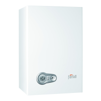
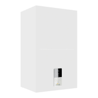
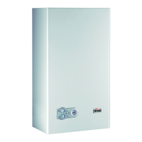
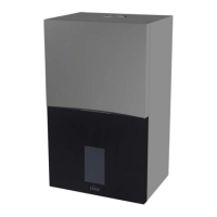
Overview of the BLUEHELIX MAXIMA heat generator, its features, and intended use.

Control Panel Overview

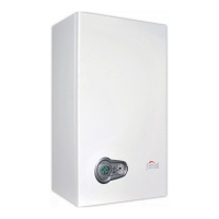
Detailed explanation of the boiler's control panel, indicators, and display elements.

Power Connection and Switching

Instructions for connecting the boiler to power and initial start-up procedures.

DHW Function Adjustment

How to enable/disable the Domestic Hot Water (DHW) function.

Heating Function Adjustment

How to enable/disable the heating function.

Temperature Settings

Adjusting DHW and heating temperatures, room temp, and ECO mode.

Pressure Management and System Draining

Restoring System Hydraulic Pressure

Procedures for managing and restoring hydraulic pressure in the heating system.

Pressure Control Screen

Explanation of the boiler's pressure control screen and its features.

System Draining Procedures

Instructions for safely draining water from the heating system.

Installation Guide

General Installation Requirements

Mandatory guidelines for qualified personnel performing boiler installation.

Site Selection and Ventilation

Criteria for choosing a safe and properly ventilated installation location.

Plumbing Connections

Steps and precautions for making plumbing connections to the boiler.

Gas Connection

Safety instructions and procedures for connecting the gas supply.

Electrical Connections

Safety instructions and procedures for electrical connections.

Fume Ducting Installation

Requirements and methods for installing fume exhaust ducts and systems.

Condensate Drain Connection

Instructions for correctly connecting the condensate drain system.

Service, Maintenance, and Troubleshooting

Adjustments and Gas Conversion

Guide to making boiler adjustments and performing gas type conversion.

Combustion Checks and Calibration

Procedures for checking combustion values and performing calibration.

Heating Power and Service Menu

Adjusting heating power and accessing the service menu for advanced settings.

System Diagnostics and Parameters

Accessing system diagnostic data and configuring transparent parameters.

Faults History and Troubleshooting

Managing fault logs, understanding error codes, and resolving issues.

Boiler Commissioning

Steps for commissioning the boiler after installation and for the first ignition.

Periodic Maintenance and Cleaning

Annual inspection checklist and guidelines for cleaning external surfaces.

Technical Data and Diagrams

Boiler Dimensions and Connections

Diagrams detailing the boiler's physical dimensions and connection points.

Installation Templates

Information on metal and paper templates for wall mounting and hole drilling.

Boiler Views and Hydraulic Circuit

Exploded views of components and the boiler's hydraulic circuit diagram.

Technical Specification Tables

Comprehensive tables of technical data, including ErP information.

Wiring and System Diagrams

Diagrams illustrating electrical wiring and system layouts for installation and troubleshooting.

Related product manuals