Instruction Manual
D103175X012
GX Valve and Actuator
July 2017
11
FIELDVUE DVC2000 Digital Valve Controller Mounting
This section provides instruction on mounting the FIELDVUE DVC2000 digital valve controller to the GX control valve.
For further detail on the operation and maintenance of the DVC2000, refer to the DVC2000 instruction manual.
The FIELDVUE DVC2000 digital valve controller mounts directly to an interface pad on the GX actuator yoke leg,
eliminating the need for mounting brackets (see figure 1). Internal passageways in the actuator route the pneumatic
output to the actuator casing, which eliminates the need for external air supply tubing in the air‐to‐open
(spring‐to‐close) constructions. (The GX will also accommodate other valve positioners, using the NAMUR mounting
pads on the side of the yoke legs.)
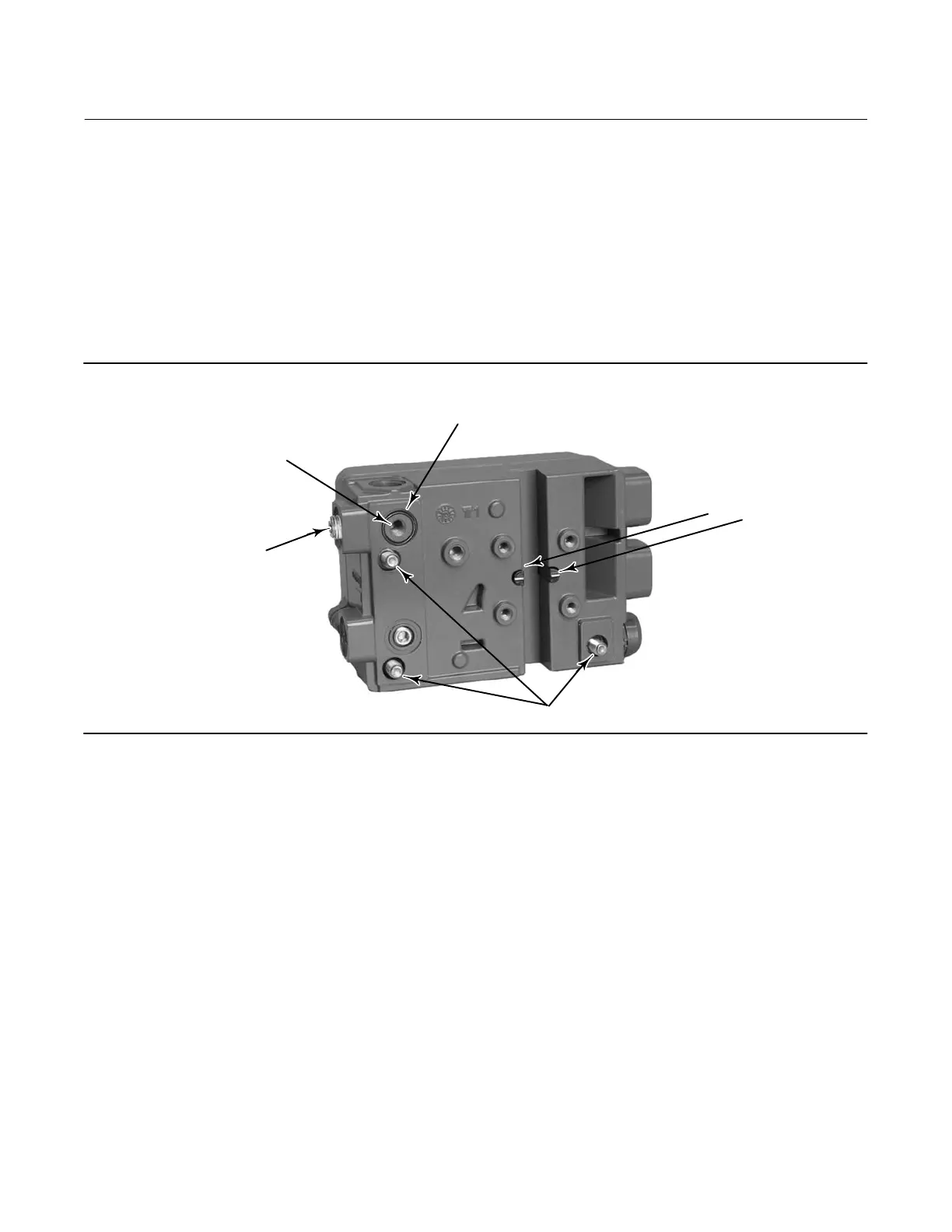
Figure 4. DVC2000 Digital Valve Controller Mounting Details
POLE PIECES
M8 MOUNTING BOLTS
A: EXTERNAL PNEUMATIC
OUTPUT PORT (1/4 NPT OR
G1/4 PLUG)
B: INTEGRAL MOUNTING
PNEUMATIC OUTPUT PORT
(R1/8 PLUG)
FOR AIR‐TO‐OPEN, INSTALL THE O‐RING SEAL BEFORE
MOUNTING TO THE GX ACTUATOR
W9019
The DVC2000 features linkage‐less position feedback when mounted to the GX control valve. There are no touching
parts between the controller and the valve stem, which simplifies controller installation. If maintenance is required,
the DVC2000 can be easily removed from the valve.
In the air‐to‐open (spring‐to‐close) configuration, the air signal to the actuator casing is supplied through the air
supply connection on the GX actuator yoke leg (see figure 18 or 19). In the air‐to‐close (spring‐to‐open) configuration,
the air signal is supplied to the actuator through the air supply connection on the top of the actuator casing (see figure
20 or 21).
For an air‐to‐open construction, a DVC2000 will mount to the actuator (figure 18 or 19). The air signal is transmitted
to the lower casing through the pneumatic passageway marked “air supply connection” in figure 18 or 19.
For an air‐to‐close construction, DN15 through DN100 (NPS 1/2 through 4) only: in the actuator design (figure 20 or
21), the pneumatic signal is connected directly to the air supply connection in the upper actuator casing. The yoke is
symmetrical and the air passageways serve as a vent, whereby the DVC2000 can be easily moved from one side of the
valve to the other without rotating the actuator.
DVC2000 Mounting Procedures
Steps A and B of the following instructions apply to the actuator construction shown in figures 18, 19, 20, and 21.

 Loading...