Instruction Manual
D103175X012
GX Valve and Actuator
July 2017
24
stretch the seal ring and work it over the top edge of the valve plug. The PTFE material in the seal ring must be
permitted time to cold‐flow during the stretching procedure, so avoid jerking sharply on this ring. Stretching the seal
ring over the valve plug may make it seem unduly loose when in the groove, but it will contract to its original size after
insertion into the bonnet.
2. Install the seat ring, valve plug/stem, bonnet and actuator yoke into the valve body by completing the assembly
according to steps 1 to 3 of the section Assembly of Unbalanced Trim.
Repair Nameplate
If required by the end‐user, an optional repair nameplate is available for recording changes made to the valve trim
during maintenance (see figure 29). This nameplate can be ordered as a spare part, and is easily mounted to the
actuator casing using a casing bolt. (Reference the Parts Ordering section of this manual.)
As shown in figure 29, the repair nameplate provides locations for maintenance personnel to record trim data, such as:
D Date of maintenance
D Trim material
D Port diameter
D Flow capacity (C
v
/ K
v
)
D Flow characteristic
D Actuator Action ATO/ATC
Bellows Maintenance
This section provides instruction on the replacement of the bellows / stem assembly (see key 49 in figure 23).
1. Remove the actuator, bonnet assembly as described in the Replacing Packing section (steps 1 through 10).
2. Remove the plug/stem assemblies as described in the Valve Trim Disassembly section (steps 2 through 6).
3. To install the new bellows / stem assembly (key 49), perform the Valve Trim Assembly (step 3).
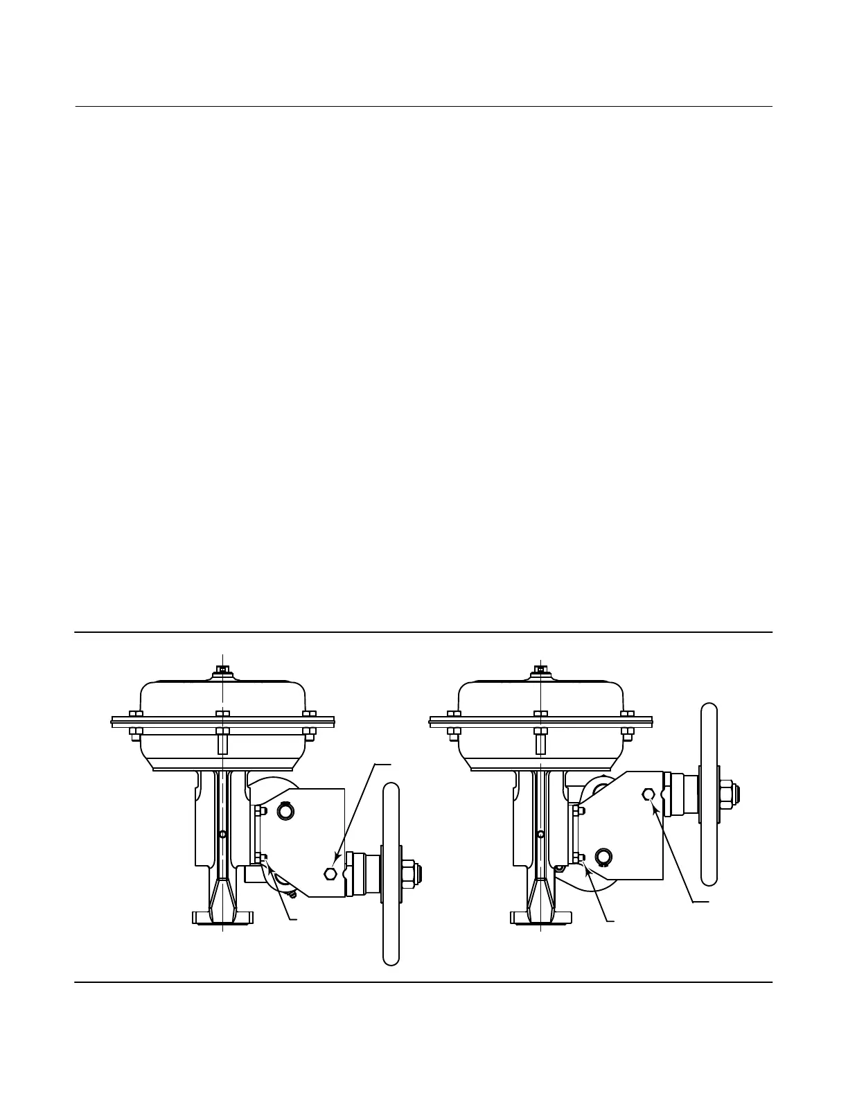
Figure 6. Fisher GX Handwheel Assembly
GE11642‐1
AIR‐TO‐CLOSE, SPRING‐TO‐OPEN
AIR‐TO‐OPEN, SPRING‐TO‐CLOSE
STUD AND
NUT (4)
STUD AND
NUT (4)
LOCKING
SCREW
LOCKING
SCREW

 Loading...