Instruction Manual
D103175X012
GX Valve and Actuator
July 2017
25
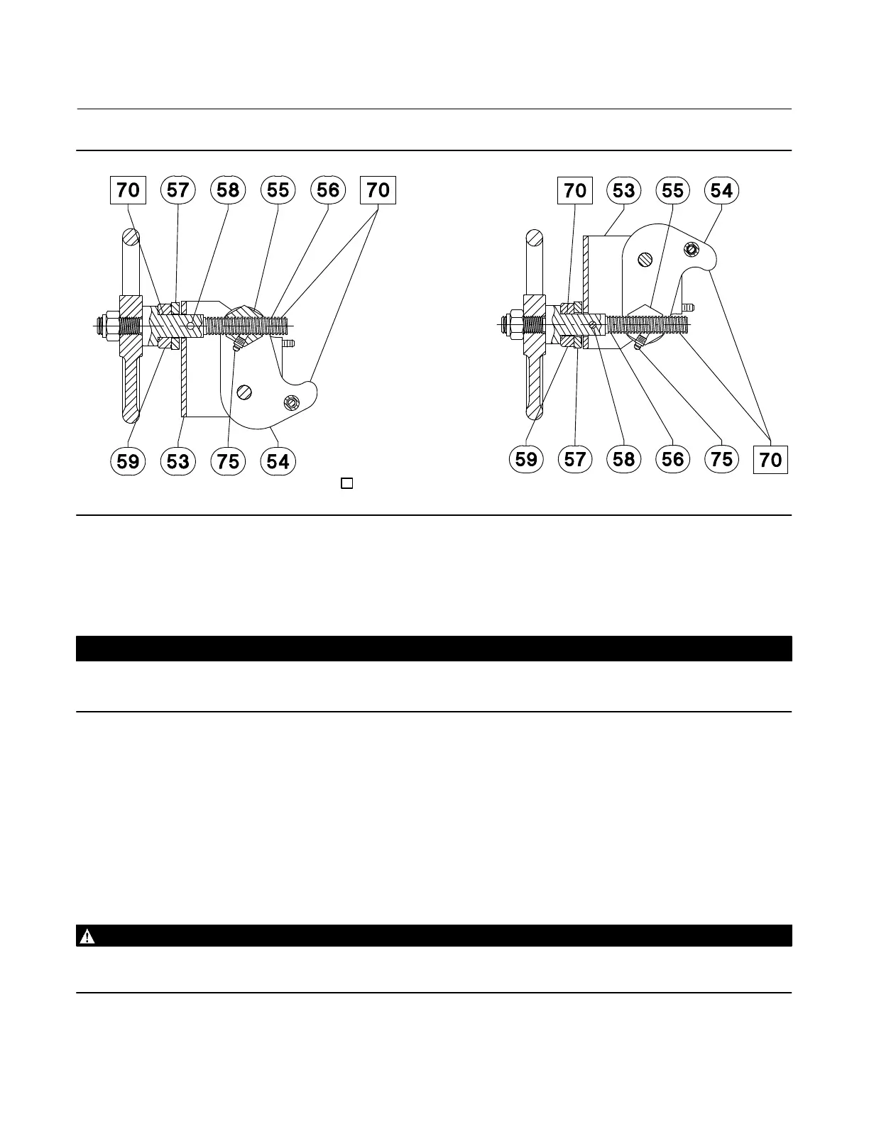
Figure 7. Fisher GX Handwheel Orientation and Grease Zerk Location
AIR‐TO‐CLOSE, SPRING‐TO‐OPENAIR‐TO‐OPEN, SPRING‐TO‐CLOSE
GE05809‐D
GE05810‐D
APPLY LUBRICANT
Handwheel Operation
CAUTION
This handwheel is designed only for use with size 225 and 750 actuators with 20 mm travel. To avoid equipment damage,
do not assemble this handwheel on size 750 actuators with 40 mm travel or size 1200 actuators.
Principle of Operation
The GX handwheel is designed to compress the actuator springs and override the actuator fail action. Turning the
handwheel drives the screw, nut, and levers. The levers push against the stem connector to transfer this motion.
Reversing the direction of the handwheel will move the nut and levers in the opposite direction. Once the levers are no
longer in contact with the stem connector, the locking screw should be used to secure the handwheel against
undesired movement. To prevent damage due to overtravel, the handwheel should not be turned more than 2 full
turns past the point at which the levers no longer contact the stem connector.
WARNING
To avoid personal injury or loss of process control due to equipment damage, ensure the levers are completely disengaged
and the locking screw is tight while the valve is in normal pneumatic operation.

 Loading...