1·4
GROUP
1 -
ENGINES
AND
EXHAUST
SYSTEM
A
1357-8
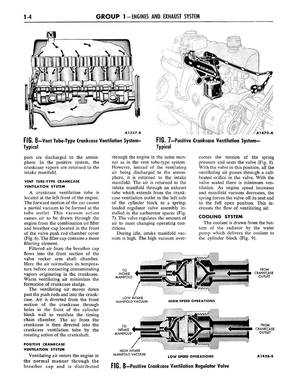
FIG.
6-Vent
Tube·Type Crank(ase Ventilation System-
Typi(al
FIG.
7-Positive Crank(ase Ventilation
System-
Typi(al
pors are discharged to
the
atmos
-
phere.
In
the
positive system,
the
crankcase
vapors
are
returned
to
the
intake manifold.
VENT TUBE-TYPE CRANKCASE
VENTILATION
SYSTEM
A
crankcase
ventilation
tube
is
located
at
the
left
front
of
the engine.
The
forward
motion
of
the
car
causes
a partial
vacuum
to be
formed
at
the
tube
outlet.
This
vacuum
act
ion
causes air
to
be
drawn
through
the
engine from
the
combination
oil filler
and
breather
cap
located in
the
front
of
the
valve
push
rod
chamber
cover
(Fig. 6).
The
filler
cap
contains
a
maze
filtering element.
Filtered
air
from
the
breather
cap
flows into
the
front
section
of
the
valve
rocker
arm
shaft
chamber.
Here
the
air normalizes its
tempera-
ture before
contacting
contaminating
vapors originating in
the
crankcase.
Warm
ventilating
air
minimizes the
formation
of
crankcase
sludge.
The
ventilating
air
moves
down
past
the
push
rods
and
into
the
crank-
case.
Air
is
diverted
from
lhe
front
section
of
the
crankcase
through
holes in
the
front
of
the cylinder
block wall
to
ventilate
the
timing
chain
chamber.
The
air
from
the
crankcase
is
then
directed
into
the
crankcase
ventilation
tube
by
the
rotating
action
of
the
crankshaft.
POSITIVE CRANKCASE
VENTILATION SYSTEM
Ventilating air
enters
the
engine in
the
normal
manner
through
the
breather
cap
and
is
distributed
through
the engine in
the
same
man-
ner
as in
the
vent tube-type system.
However, instead
of
the ventilating
air being discharged to
the
atmos-
phere,
it
is
returned to the intake
manifold.
The
air
is
returned
to
the
intake manifold through an exhaust
tube which extends from the
crank-
case ventilation outlet in
the
left side
of the cylinder block
to
a sprin
g-
loaded regulator valve assembly in-
stalled in
the
carburetor
spacer
(Fig.
7).
The
valve regulates
the
amo
unt
of
air to meet changing operating con-
ditions.
During
idle, intake manifold vac-
uum
is
high.
The
high
vacuum
over-
TO
INTAKE
MANifOLD
comes the tension of the spring
pressure
and
seats
the
valve (Fig. 8).
With
the valve in this position, all the
ventilating
air
passes
through
a caJi-
bra
ted orifice in
the
valve.
With
the
valve seated
there
is
minimum
ven-
tilation.
As
engine
speed
increases
and
manifold
vacuum
decreases, the
spring forces
the
valve off its seat and
to
the
full
open
position.
This
in-
creases
the
flow
of
ventilating air.
COOLING
SYSTEM
The
coolant
is
drawn
from
the
bot-
tom
of
the
radiator
by
the
water
pump
which delivers
the
coo
lant to
the
cylinder
block (Fig. 9).
fROM
CRANKCASE
OUTlET
lOW
INTAKE
MANifOLD
VACUUM
HIGH
SPEED
OPERATIONS
TO
I
NTAKE
MANifOLD
HIGH
INTAKE
MANifOLD
VACUUM
LOW
SPEED
OPERATIONS
FIG.
8-Positive
Crank(ase Ventilation Regulator
Valve
fROM
CRANKCASE
OUTlET
A1458-B
 Loading...