4. Insert the upper bearing re-
moval tool (tool 6331) in the oil hole
in the crankshaft.
5. Rotate the crankshaft in the di-
rection
of
engine rotation
to
force the
bearing
out
of
th
e block.
6. Clean the crankshaft journal.
When
replacing
standard
bearings
with new bearings, it is good practice
to first
try
to
obtain
the
proper
clear-
ance
with two
blue
bearing
halves.
7.
To
install the
upper
main bear-
ing, place the plain end
of
the bearing
over the
shaft
on the locking tang
side
of
the block. Using tool 6331 in
the oil hole in the
crankshaft,
rotate
the
crankshaft
in
the
opposite direc-
tion
of
engine rotation until the bear-
ing seats itself. Remove the tool.
8. Replace
the
cap
bearing.
9. Support the
crankshaft
so
that
its weigbt will
not
compress the Plas-
ligage
and
provide
an
erroneous
reading.
Position a jack so
that
it will
bear against the counterweight
ad-
joining the bearing which
is
being
checked.
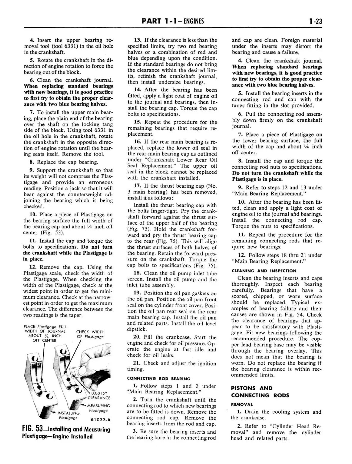
10. Place a piece
of
Plastigage on
the bearing surface the fu
ll
width
of
the bearing cap
and
about
JA
inch off
center (Fig. 53).
11. Install the cap
and
torque
the
bolts to specifications.
Do
not
tum
the crankshaft while the Plastigage is
in place.
12. Remove the cap. Using the
Plastigage scale, check
th
e width
of
the Plastigage.
When
checking the
width
of
the Plastigage, check at the
widest point in
order
to get the mini-
mum clearance. Check at the narrow-
est point in
order
to
get the
maximum
clearance.
The
difference between the
two readings
is
the taper.
PLA
CE
Plo
sl"
go
ge
FULL
WI
DTH
OF
JOURNAL
A80UT
1/4
INCH
OFF
C
ENTER
C
HE
CK WIDTH
OF
Plosligoge
P/osli
goge
P/o
st
igog
e
A 1
022-A
FIG.
53-Installing
and Measuring
Plastigage-Engine
Installed
PART
1-1-
ENGINES
13.
If
th
e clearance
is
less
than
the
specified limits, try two red bearing
halves
or
a combination
of
r
ed
and
blue depending upon the condition.
If
tbe
standard
bearings do not bring
the clearance with
in
the desired lim-
its, refinish the crankshaft
journa
l,
then install undersize bearings.
14.
After
the bearing has been
fitted, apply a light
coat
of
engine oil
to the journal and bearings, then
in-
sta
ll
the bearing cap.
Torque
the cap
bolts to specifications.
15. Repeat the procedure for the
remaining bearings
that
require re-
placement.
16.
If
the rear main bearing
is
re-
placed, replace the lower oil seal
in
the rear ma
in
bearing
cap
as outlined
under
"
Crank
s
haft
Lower Rear Oil
Se
al Repla
cement."
The
upper
oil
seal
in
the block
cannot
be replaced
with the
crankshaft
in
stalled.
17.
If
the thrust bearing
cap
(No.
3 main bearing) has been removed,
install it as follows:
Install the thrust bearing
cap
with
the bolts finger-tight.
Pry
the
crank-
shaft forward against the thrust sur-
face
of
the upper
half
of
the bearing
(Fig. 75). Hold the crankshaft
for-
ward and pry the thrust bearing cap
to the rear (Fig. 75). This will a
li
gn
the thrust surfaces
of
both halves
of
the bearing. Retain the forward pres-
sure on the crankshaft.
Torque
the
cap bolts to spec
ific
ations (Fig. 75).
18. Clean the oil
pump
in
l
et
tube
screen.
In
stall the oil
pump
and
the
inlet tube assembl
y.
19.
Po
sition the
oi
l pan gaskets on
the o
il
pan. Position the oil pan front
seal on the cylin
der
front cover. Posi-
tion the oil pan rear seal on the rear
main bearing ca
p.
Install the oil pan
and related part
s.
Install the oil level
dipstick.
20. Fi
ll
the crankcase.
Start
the
engine and check for oil pressure.
Op-
erate the eng
in
e
at
fast idle
and
check for oil
le
ak
s.
21. Check and adjust the ignition
timing.
CONNECTING
ROD BEARING
1. Follow steps I and 2
under
"Ma
in
Bearing Replacement."
2.
Turn
the crankshaft until the
connecting rod to which new bearings
are to be fitted is down. Remove the
connect
in
g rod ca
p.
Remove the
beari
ng
in
serts from the rod and cap.
3. Be sure the bearing inserts
and
the bearing bore
in
the connecting rod
1-23
and
cap
are clean.
Foreign
material
under
the
inserts m
ay
distort the
bearing
and
ca
use a failure.
4. Clean the
crankshaft
journal.
When
replacing
sta
ndard
bearings
with new bearings,
it
is good practice
to
first
try
to
obtain
the
proper
clear·
ance
with
two
blue bearing halves.
5.
In
stall the bearing inserts in the
co
nnecting rod
and
cap
with the
tangs fitting in the slot provided.
6.
Pull the connecting rod assem-
bly
down
firmly
on
the
cra
nkshaft
journal.
7.
Place a piece
of
Plastigage on
the l
ower
bearing surface, the full
width
of
the
cap
and
abou
t
Y<a
inch
off center.
8.
In
stall the
cap
and
torque
the
connecting rod nuts
to
specifications.
Do
not
turn
the
crankshaft
while the
Plastigage is in place.
9. Refer to steps
12
and
13
under
"Main
Bearing Replacement."
10.
After
the bearing has been fit-
ted, clean
and
apply a light coat
of
engine oil to the journal
and
bearings.
In
sta
ll
the
connec
ting rod cap.
Torque
the nuts to specifica
ti
ons.
11.
Repeat
the
procedure
for the
remaining connecting rods that
re-
quire new bearings.
12. Follow steps
18
thru
21
under
"
Main
Bearing Replacement."
CLEANING
AND
INSPECTION
Clean
the bearing inserts
and
caps
thoroughly.
In
spect each bearing
carefu
ll
y. Bearings
that
have a
scored, chipped,
or
worn
surface
should be replaced. Typical
ex-
amples
of
bearing failure and their
causes are shown
in
Fig. 54. Check
the cl
earance
of
bearings
that
ap-
pear
to
be satisfactory with Plasti-
gage. F it new bearings following the
recommended
procedure.
The
cop-
per
lead bearing base
may
be visible
through
the bearing overlay. This
does not mean
that
the bearing
is
worn.
Do
not replace the bearing if
the bearing clearance
is
wi
thin rec-
ommended
limit
s.
PISTONS AND
CONNECTING RODS
REMOVAL
1.
Drain
the
coo
ling system and
the
crankca
se.
2. Refer to
"Cylinder
Head
Re-
moval" and remove
th
e cylinder
head and related parts.
 Loading...