1-14
GROUP
1-
ENGINES
AND
EXHAUST
SYSTEM
~
."
SPRING
C
llP~
~
PPER
NUT
RETAINER
~IN
SUlATOR
'
1P!l~
.
LEAF
·
SPRING
SUPPORT~
'
.
ASSEMB
.
lY
BRACKET
....::,~
'~.
\
~
-
~
RUBBER
Fl:T
~
WASHER
.
Jaiy
C
EN
TER
BOLT
lOWER~~
INSULA
TOR
A1521-A
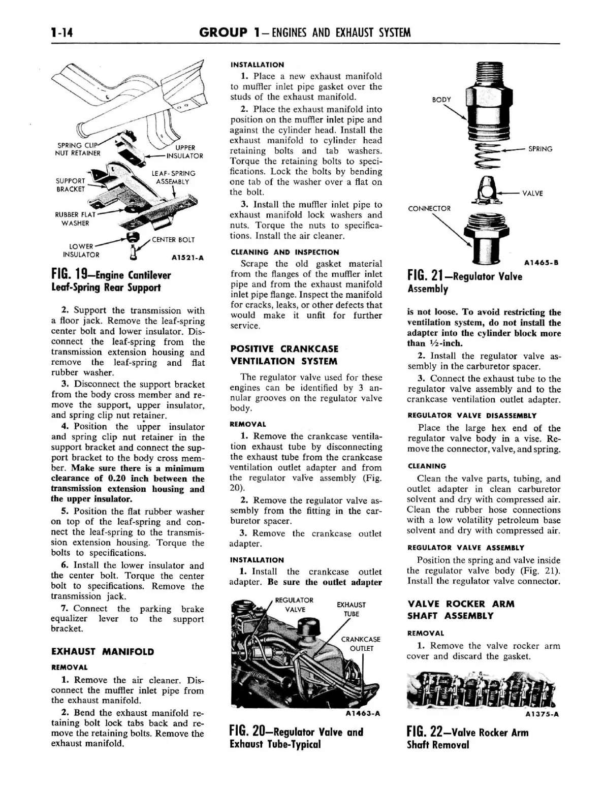
FIG.
19-Engine
Cantilever
Leaf-Spring
Rear
Support
2.
Support
the
transmi
ssion with
a floor jack. Remove the leaf-spring
center
bolt
and lower insulator. Dis-
connect the leaf-spring from the
transmiss
ion
extensi
on
housing
and
remove the leaf-spring
and
flat
rubber washer.
3.
Disconnect
the
support
bracket
from the
body
cross
member
and
re-
move
the
suppo
rt,
upper
insulator,
and
spring
clip
nut
retainer.
4. Position the upper insulator
and
spring clip
nut
r
etainer
in
the
support
bracket
and
connect
the
sup-
port
bracket
to
the
body
cross
mem-
her.
Make
sure
there is a
minimum
clearance
of
0.20
incb
between
tbe
transmission extension
housing
and
tbe
upper
insulator.
5.
Po
sition
the
flat
rubber
washer
on
top
of
the leaf-s
pring
and
con-
nect
the leaf-spring to the transmis-
si
on
extension housing.
Torque
the
bolts to spec
ifi
cations.
6. Install
the
lower
insulator
and
the
center
bolt.
Torque
the
center
bolt to specifications. Remove
the
transmission
jack
.
7.
Co
nn
ect
the
equalizer
lever
bracket
.
parking
brake
to
the
s
upport
EXHAUST
MANIFOLD
REMOVAL
1.
Remove
the
air
cleaner.
Dis-
connect
the
muffler inlet
pipe
from
the
exhau
st
manifold
.
2. Bend the
exhaus
t
manifold
re-
taining
bolt
lock
tabs
back
and
re-
move
the
retaining
bolts.
Remove
the
exhaust
manifold.
INSTAllATION
1. Place a new
exhaust
manifold
to
muffler inlet pipe gasket
over
the
s
tud
s
of
the exhaust manifold.
2.
Pl
ace the exhaust
manifold
into
po
sition
on
the muffler inlet pipe
and
against the cylinder head.
In
stall the
exhau
st manifold to cylinder head
retaining bolts and tab washers.
Tor
que the retaining bolts to speci-
fic
a
ti
on
s.
Lock the bolts by bending
one
tab
of
the was
her
over a flat
on
the boll.
3.
]n
sta
ll
the muffler inlet pipe to
exhaust manifold lock washers
and
nut
s.
Torque
the nuts to specifica-
tion
s.
Insta
ll
the air cleaner.
CLEANING
AND
INSPECTION
Scrape
th
e old gasket material
from
the
fl
anges
of
the
muffler inlet
pipe and from the exhaust
manifold
inlet pipe flange.
In
spect
the
manifold
for
cracks
, leaks,
or
other
defects
that
would make it unfit
for
further
service.
POSITIVE CRANKCASE
VENTILATION SYSTEM
The
reg
ulator
va
lv
e used for these
engines can
be
id
entified by 3 an-
nular grooves
on
the reg
ul
a
tor
valve
body.
REMOVAL
1. Remove the
crankcase
ventila-
tion
exhaust
tube by disconnecting
the
exhau
st tube
from
the
crankcase
ventilation outlet
ada
pter a
nd
from
the
regulator valve assembly (Fig.
20).
2.
Remove
the regulator valve as-
sembly
from
the fitting in
the
car
-
buretor
spacer.
3.
Remove the crankcase outlet
adapter.
INSTALLATION
1. I nsta
ll
the
crankcase
outlet
adapter
. Be sure the
outlet
adapter
FIG.
20-Regulator
Valve
and
Exhaust
Tube-
Typi(al
.,.-.:;_~_-
SPRING
a--
VAlV
E
A146,_B
FIG.
21-Regulalor
Valve
Assembly
is
not
loose.
To
avoid
restricting the
ventilation system,
do
not
install
tbe
adapter
into
the
cylinder
block
more
than
1/2
-inch.
2.
Inst
a
ll
the
regulator
valve as-
sembly in
the
carburetor
spacer
.
3.
Connect
the
exhaust
tube
to the
regulator
valve assembly
and
to
the
crankcase
ventilation
outlet
adapter.
REGULATOR VALVE DISASSEMBLY
Place
the
large hex
end
of
the
regula
tor
valve
body
in a vise. Re-
move
the
connector
, valve,
and
spring.
CLEANING
Clean
the valve parts,
tub
ing,
and
outlet
ada
pter
in
clean
carburetor
so
lvent
and
dr
y with compressed air.
Cl
ean
the
rubber
hose connections
with a l
ow
volatility petroleum base
solvent
and
dry with
compressed
air.
REGULATOR VALVE ASSEMBLY
Position the s
pring
and
valve inside
the
regulator
valve body (Fig. 2
1).
In
stall the
regulator
valve connector.
VALVE
ROCKER
ARM
SHAFT ASSEMBLY
REMOVAL
1. Remove the valve
rocker
arm
cov
er
and
discard
th
e gasket.
FIG.
22-Valve
Ro(ker
Arm
Shaft
Removal
 Loading...