FIG.
23-Valve
Rocker
Arm
(over
Gasket
Installation
2. Loosen all the valve
rocker
arm
adjusting screws two
turn
s
at
a time
in
sequence, to remove the valve
spring
lo
ad from the
rocker
arms. Re-
move the valve
rocker
arm s
haft
assembly
(F
i
g.
22).
INSTALLATION
1.
App
ly Lubriplate
to
both
ends
of
the push rods
and
to the valve st
em
tip.
2.
Po
si
tion the valve rock
er
arm
shaft assembly on the he
ad
.
3. Tighten a
ll
the valve r
ocker
arm
shaft retaining bolts two turns at a
time in sequence.
Torque
the bolts to
spec
ifi
cations.
4. P
erform
a preliminary valve
lash adjustment.
5. Clean the valve
ro
cker
arm
cover.
Coa
t one side
of
a new valve
rocker
arm
cover gasket with oil re-
sistant sealer. Lay the cemented side
of
the gasket
in
place in the cover
(Fig. 23).
In
sta
ll
the
cover,
making
sure that the gasket seats evenly
around the head.
The
cover is tight-
ened
in
two steps.
Fir
st
torque
the
retaining bolts to specifications.
Two
minutes after the initial
ti
ghtening,
torque the bolts to the same
specifica-
tion.
DISASSEMBLY
1. Remove the pin and spring
washer from each end
of
the valve
rocker arm shaf
t.
PART
1-1-
ENGINES
2. Slide the valve
rocker
arms,
springs,
and
supports off the shaft. Be
sure to identify
th
e
part
s.
3.
If
it
is
necessary to remove
the
plugs from each end
of
the shaft.
drill
or
pierce the plug on
one
end.
Use a steel rod
to
knock
out
the plug
on the opposite end. Working from
the open end, knock
out
th
e remain-
ing plug.
CLEANING AND INSPECTION
Clean a
ll
the parts thoroughly.
Make sure that a
ll
oil passages are
open.
Check the clearance between each
rocker
ar
m and
th
e shaft by check-
in
g the
10
of
th
e rocker a
rm
bore
and
th
e
00
of
the shaft.
If
the clear-
ance between any rocker
ar
m and the
sh
aft
exceeds the wear limit, replace
the
sh
aft
and
/ or the rocker arm. In-
spect the sh
aft
and
the
rocker
bore
for nicks, scratches, scores, or scuff
s.
Dress
up
minor surface defects with
a hone.
Insp
ec
t the
pad
at the valve end
of
the
rocker
arms for a grooved
radius.
If
the pad
is
grooved, replace
the rocker arm.
Do
not
a
ttempt
to
tru
e this surface by grinding.
ASSEMBLY
1. Lubricate all parts with engine
oil. Apply
Lubrip
late to the valve and
push rod ends
of
the rocker arm.
2.
If
the plugs were removed from
the ends
of
the sh
af
t, use a blunt tool
or
large
di
ameter pin
punch
and
in-
sta
ll
a plug,
cup
side out, in
each
end
of
the shaft.
3.
In
sta
ll
the spring washer
and
pin on
one
end
of
the shaft.
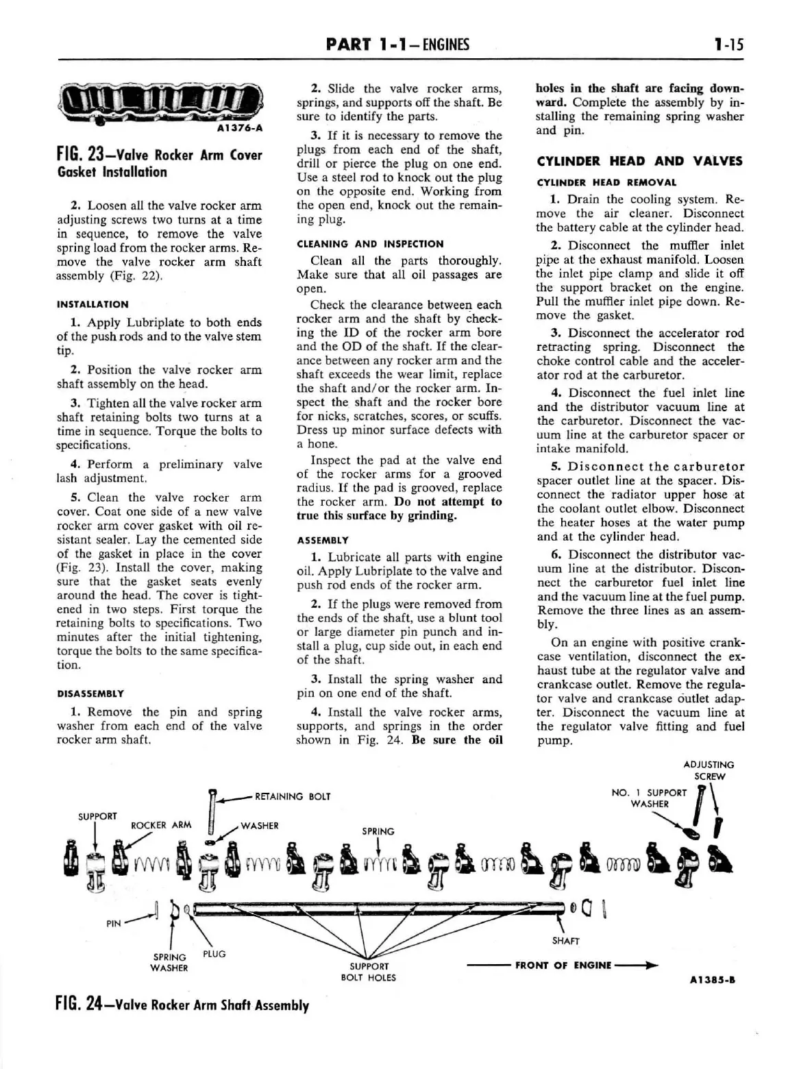
4.
In
stall the valve
rocker
arms,
supports, and springs in the
order
shown
in
Fig. 24. Be sure the oil
1-15
holes
in
th
e
shaft
are facing down-
ward.
Co
mplete the assembly by in-
sta
lling the
r~m
a
ining
spring wash
er
and
pin
.
CYLINDER
HEAD
AND
VALVES
CYLINDER HEAD REMOVAL
1.
Dr
a
in
the cooling system. Re-
move
the
air cleaner. Disconnect
the battery cable
at
the
cylinder head.
2.
Di
sco
nnect
the
muffler inlet
pipe
at
the
exhaust
manifold. Loosen
the inlet pipe
clamp
and
slide it off
the su
pport
bracket
on
the
engine.
Pull the muffler inlet pipe
down
. Re-
move
the
gasket.
3.
Di
sconnect the accel
erator
rod
retracting spring. Disco
nne
ct the
c
hoke
control cable and the acceler-
ator
rod
at
the
carburetor.
4.
Dis
con
nect
the fuel inlet line
and
the
dis
tributor
vacuum
line at
the
carbure
tor. Disconnect the vac-
uum
line at the
carburetor
spacer
or
int
ake
manifold.
5.
Disco
nn
ect
the
carburetor
spacer
out
l
et
line
at
the spacer. Dis-
connect the r
ad
iat
or
upper
hose ·at
th
e coola
nt
out
l
et
elbow. Disconnect
the heater hoses
at
the water
pump
and
at the cylinder head.
6. Disco
nnect
the distributor vac-
uum
line at the distributor. Discon-
nect the ca
rburetor
fuel inlet line
and
the vacuum line at the fuel
pump.
Remove the three lines as an assem-
bly.
On
an engine with positive
crank-
case ventilation, disconnect the ex-
hau
st
tube
at
the regulat
or
va
lv
e and
crankcase
outlet. Remove the regula-
tor
va
lv
e a
nd
crankcase outlet adap-
ter. Disco
nn
ect the vacuum line at
the regul
ator
va
lve fitting
and
fuel
pump
.
ADJUSTING
SCREW
NO.
1
SUP
PORT
I \
WASH
ER
t:
RETAINING
BOLT
SUPPOR
T
~
R
OCK
ER
ARM
~
WASHER SPRING
I
~
~
V1
~
i
&
rY
m
l
i
ta
Jm
!&
i!l
rrrrn
~S?
~,
.
mm
llt~
PlN~
P\t;;;;
5
~
;;;:
(Va \
l \ SHAFT
SPRING
PLUG
WASHER
SUPPORT
---
fRONT
Of
ENGINE
--
...
~
SOlT
HOLES
It.
1385.1
FIG.
24-Valve
Ro(ker
Arm
Shaft
Assembly
 Loading...