7-01
Cooling System
7-01
PART
7
Cooling System
COMPONENT INDEX
Page
COMPONENT INDEX Page
DESCRIPTION AND OPERATION . . . . . . . . .
7-01
Drive Belt . . . . . . . . . . . . . . . . . . . . . . . . . . 7-01
ADJUSTMENTS . . . . . . . . . . . . . . . . . . . . . . .
7-01
Belt Tension . . . . . . . . . . . . . . . . . . . . . . . .
7-01
DESCRIPTION AND OPERATION
The system is of the full flow type with a centrifugal pump. The
thermostat, located in the cylinder head, controls the flow through
the system maintaining the proper temperature.
The coolant flow is from the bottom of the radiator to the pump
which delivers it to the cylinder block. It then flows through the
cored passages to cool the entire length of each cylinder wall.
Upon reaching the rear of the cylinder block, the coolant is
directed upward into the cylinder head where it cools the combus-
tion chambers, valves and valve seats.
The coolant from the cylinder head flows past the thermostat, if
it is open, through the coolant outlet housing and into the top of the
radiator.
Another passage in the head routes the warm coolant through
the intake manifold to help atomize the fuel mixture, and then
through a hose to the inlet hose of the water pump.
ADJUSTMENTS
DRIVE BELT
The fan drive belt should be properly adjusted at all times. A
loose drive belt can cause improper alternator, fan and water pump
operation. A belt that is too tight places a severe strain on the water
pump and the alternator bearings.
A properly tensioned drive belt minimizes noise and also pro-
longs the service life of the belt. Therefore, it is recommended that
a belt tension gauge be used to check and adjust the belt tension.
Any belt that has been operated for a minimum of 10 minutes
is considered a used belt, and when adjusted, it must be
adjusted to the used tension shown in the specifications.
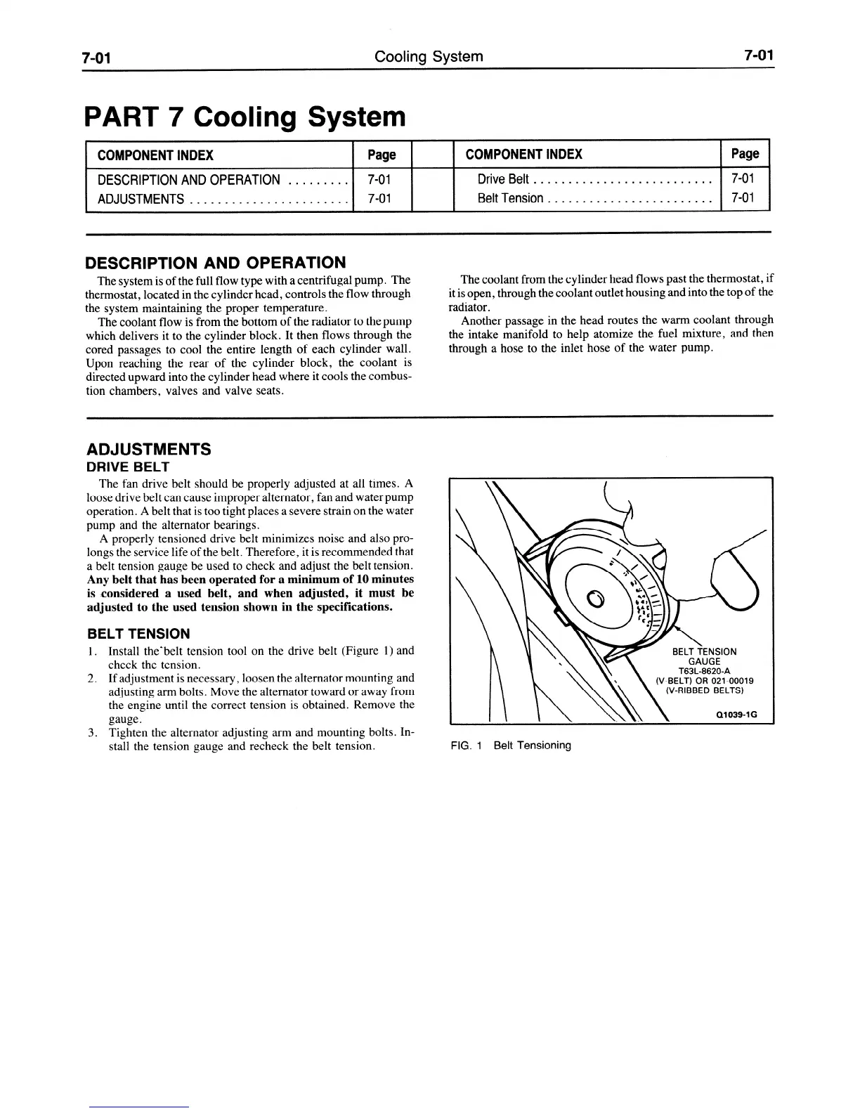
BELT TENSION
1. Install the”belt tension tool on the drive belt (Figure 1) and
check the tension.
2. If adjustment is necessary, loosen the alternator mounting and
adjusting arm bolts. Move the alternator toward or away from
the engine until the correct tension is obtained. Remove the
gauge.
3. Tighten the alternator adjusting arm and mounting bolts. In-
stall the tension gauge and recheck the belt tension.
T63L-8620-A
(V-BELT) OR 021-00019
(V-RIBBED BELTS)
01039-1G
FIG. I Belt Tensioning
 Loading...