02-3
lanition Svstem - Distributorless
02-3
DESCRIPTION AND OPERATION
WARNING
. HIGH VOLTAGE PRODUCED BY A
DISTRIBUTORLESS IGNITION SYSTEM IS HIGHER
THAN FOR A CONVENTIONAL IGNITION SYSTEM.
. WHEN CARRYING OUT SERVICE OPERATIONS ON
AN ENGINE EQUIPPED WITH DISTRIBUTORLESS
IGNITION, IT IS IMPORTANT TO BE AWARE OF THE
ABOVE POINT AS WELL AS ALL THE USUAL
SAFETY MEASURES TO PREVENT THE
POSSIBILITY OF ELECTRIC SHOCKS.
The purpose of an engine’s ignition system is to ignite the
fuel/air mixture at the correct time and sequence based
upon the input it receives.
The Distributorless Ignition System (DIS) used on the VSG
411/413 engines is a state-of-the-art ignition system. The
brain of this system is the Ignition Control Module (ICM),
also known as the Universal Electronic Spark Control
(UESC) module. This module normally receives four
inputs:
From these inputs, the ICM computes spark strategy
(spark advance) to obtain optimum engine performance for
correct input conditions.
With this system, the electronic control module monitors
the engine load, speed, and operating temperature and
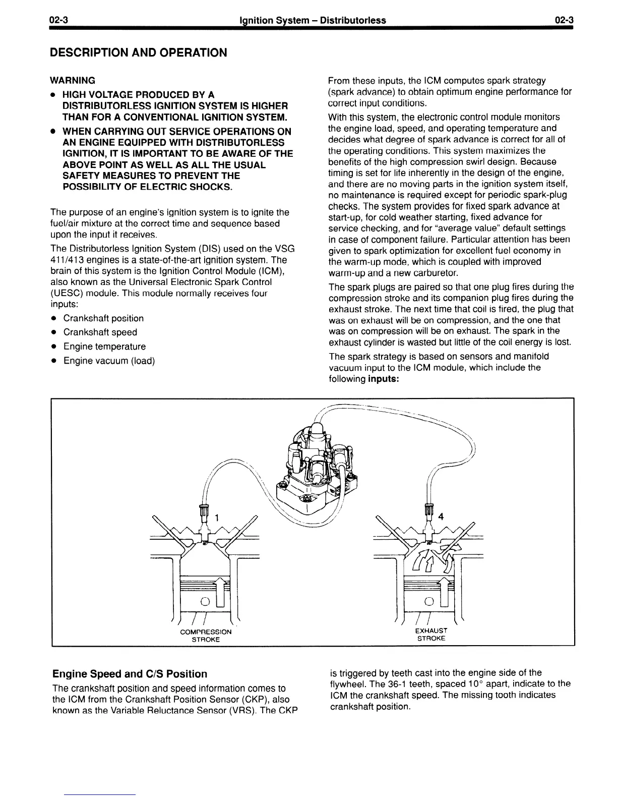
was on exhaust will be on compression, and the one that
decides what degree of spark advance is correct for all of
the operating conditions. This system maximizes the
was on compression will be on exhaust. The spark in the
benefits of the high compression swirl design. Because
timing is set for life inherently in the design of the engine,
exhaust cylinder is wasted but little of the coil energy is lost.
and there are no moving parts in the ignition system itself,
no maintenance is required except for periodic spark-plug
The spark strategy is based on sensors and manifold
checks. The system provides for fixed spark advance at
vacuum input to the ICM module, which include the
start-up, for cold weather starting, fixed advance for
service checking, and for “average value” default settings
in case of component failure. Particular attention has been
given to spark optimization for excellent fuel economy in
the warm-up mode, which is coupled with improved
warm-up and a new carburetor.
The spark plugs are paired so that one plug fires during the
compression stroke and its companion plug fires during the
exhaust stroke. The next time that coil is fired, the plug that
l
Crankshaft position
l
Crankshaft speed
l
Engine temperature
l
Engine vacuum (load)
following
inputs:
COMPRESSION
EXHAUST
STROKE
STROKE
Engine Speed and C/S Position
The crankshaft position and speed information comes to
the ICM from the Crankshaft Position Sensor (CKP), also
known as the Variable Reluctance Sensor (VRS). The CKP
is triggered by teeth cast into the engine side of the
flywheel. The 36-1 teeth, spaced IO” apart, indicate to the
ICM the crankshaft speed. The missing tooth indicates
crankshaft position.
 Loading...