01-23
Basic Enaine
01-23
REMOVAL AND INSTALLATION (Continued)
Installation
1.
If crankshaft sprocket was removed, install using the
pulley, bolt and washer. The timing mark on the
sprocket must face the end of the crankshaft.
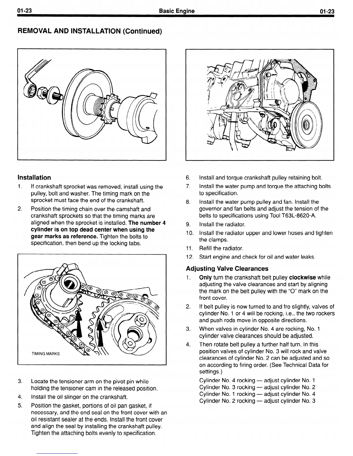
2.
Position the timing chain over the camshaft and
crankshaft sprockets so that the timing marks are
aligned when the sprocket is installed.
The number
4
cylinder is on top dead center when using the
gear marks as reference.
Tighten the bolts to
specification, then bend up the locking tabs.
3.
Locate the tensioner arm on the pivot pin while
holding the tensioner cam in the released position.
4.
Install the oil slinger on the crankshaft.
5.
Position the gasket, portions of oil pan gasket, if
necessary, and the end seal on the front cover with an
oil resistant sealer at the ends. Install the front cover
and align the seal by installing the crankshaft pulley.
Tighten the attaching bolts evenly to specification.
6.
Install and torque crankshaft pulley retaining bolt.
7. Install the water pump and torque the attaching bolts
to specification.
8. Install the water pump pulley and fan. Install the
governor and fan belts and adjust the tension of the
belts to specifications using Tool T63L-8620-A.
9.
Install the radiator.
10.
Install the radiator upper and lower hoses and tighten
the clamps.
11. Refill the radiator.
12.
Start engine and check for oil and water leaks.
Adjusting Valve Clearances
1.
Only
turn the crankshaft belt pulley
clockwise
while
adjusting the valve clearances and start by aligning
the mark on the belt pulley with the “0” mark on the
front cover.
2. If belt pulley is now turned to and fro slightly, valves of
cylinder No. 1 or 4 will be rocking, i.e., the two rockers
and push rods move in opposite directions.
3.
When valves in cylinder No. 4 are rocking, No. 1
cylinder valve clearances should be adjusted.
4. Then rotate belt pulley a further half turn. In this
position valves of cylinder No. 3 will rock and valve
clearances of cylinder No. 2 can be adjusted and so
on according to firing order. (See Technical Data for
settings.)
Cylinder No. 4 rocking - adjust cylinder No. 1
Cylinder No. 3 rocking - adjust cylinder No. 2
Cylinder No. 1 rocking - adjust cylinder No. 4
Cylinder No. 2 rocking - adjust cylinder No. 3
 Loading...