01-29
Basic Enaine
01-29
DISASSEMBLY AND ASSEMBLY
Engine Assembly
Disassembly
1.
2.
Mount the engine on a stand and drain crankcase.
Disconnect the fuel line at the fuel pump and
carburetor.
3. Disconnect the spark plug leads, remove them from
the clip on the rocker cover and position out of the
way.
4.
5.
Disconnect the water outlet and crankcase ventilation
hoses at the intake manifold.
Disconnect the wire from the temperature gauge
sending unit.
6.
7.
Disconnect the throttle rod from the carburetor.
Remove the governor mounting bolts and remove
governor and drive belt.
8.
9.
10.
11.
12.
Remove the thermostat housing and thermostat.
Remove the rocker arm cover and gasket.
Remove the rocker arm shaft bolts evenly and lift off
the rocker arm, shaft assembly.
Lift out the push rods from their locations and keep
them in their correct order.
Remove the cylinder head bolts and lift off the cylinder
head and gasket. Do not lay the cylinder head flat on
its face as damage to the spark plugs or gasket
surface can occur.
13.
14.
15.
16.
17.
18.
19.
Remove the fuel pump and oil pump.
Remove the dipstick and tube.
Remove the secondary wiring.
Remove fan, spacer, pulley and generator belt.
Remove the generator mounting and adjusting
bracket bolts. Remove generator.
Remove crankshaft pulley.
Remove tne water pump, front cover and crankshaft
oil slinger.
20. Remove any ridge and/or carbon deposits from the
upper end of the cylinder bores. Move the piston to
the bottom of its travel and place a cloth on the piston
head to collect the cuttings. Remove the cylinder
ridge with a ridge cutter. Follow the instructions
furnished by the tool manufacturer.
Never cut into
the ring travel area in excess of 0.8 mm (l/32 inch)
when removing ridge.
21.
Invert the engine on the stand and remove the oil pan
and gaskets.
22.
23.
24.
25.
26.
.
Remove the oil pick up tube and screen.
Remove the flywheel and tear engine plate.
Remove the tear bearing retainer.
Remove the timing chain tensioner.
Remove the camshaft sprocket and timinq chain.
27.
28.
29.
30.
31.
32.
33.
34.
Remove the camshaft thrush plate and the camshaft.
Remove the tappets keeping them in their correct
order.
Make sure all connecting rods and caps are marked
so that they can be installed in their original locations.
Partially loosen the connecting rod bolts several turns
and tap them to release the bearing caps. Remove
the bolts completely and remove the caps. Push the
pistons out of the bores and remove the assemblies.
Remove the main bearing caps bolts evenly and lift off
each cap. Lift out the crankshaft and handle with care
to avoid possible fracture or damage to finished
surfaces.
Remove the main bearings from block and cap.
Remove the thrust washers.
Disassemble the piston and connecting rod
assemblies. Remove the piston rings and the two
piston pin snap rings. Push the piston pin out of each
piston.
Remove the coolant drain plug and oil pressure
sending unit from the block.
Remove the block from the stand.
Assembly
When installing nuts or bolts that must be tightened (refer
to the torque specifications), oil the threads with light weight
engine oil.
Do not oil threads that require oil-resistant or
water-resistant sealer.
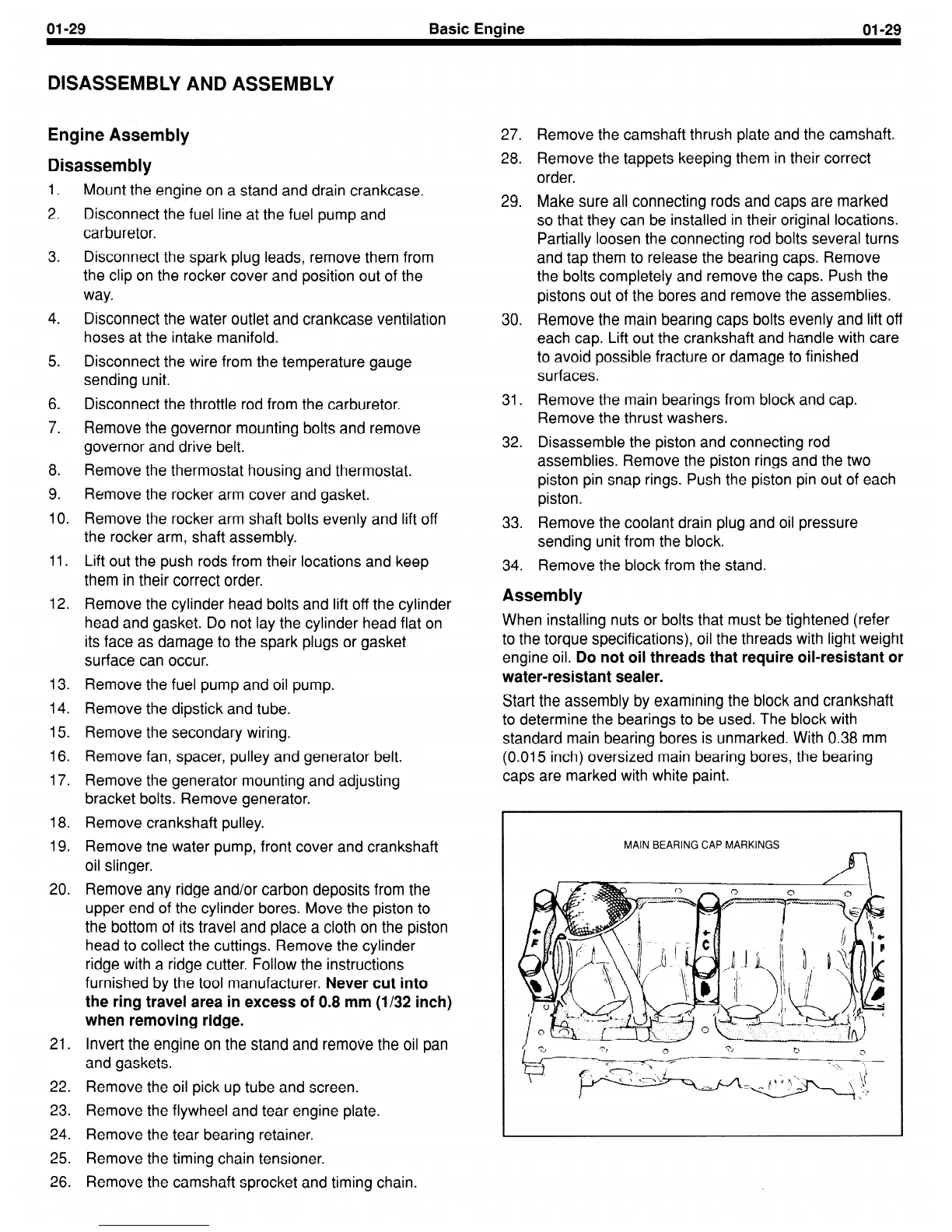
Start the assembly by examining the block and crankshaft
to determine the bearings to be used. The block with
standard main bearing bores is unmarked. With 0.38 mm
(0.015 inch) oversized main bearing bores, the bearing
caps are marked with white paint.
MAIN BEARING CAP MARKINGS
 Loading...