Home
Fronius
Portable Generator
TransSteel 2500c
Fronius TransSteel 2500c User Manual
4
of 1
of 1 rating
120 pages
Give review
Manual
Specs
To Next Page
To Next Page
To Previous Page
To Previous Page
Loading...
38
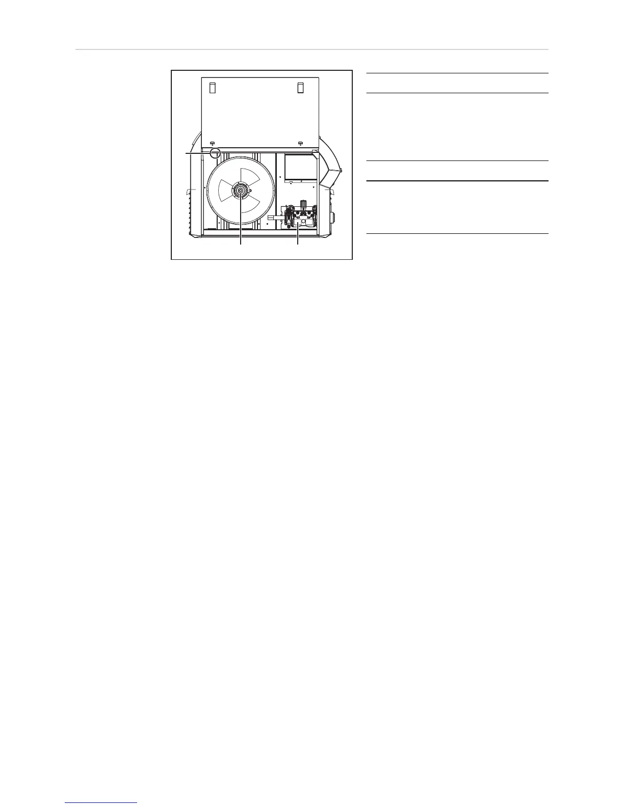
Side view
No.
Function
(1)
Wirespool holder with brake
for holding standard wirespools
with a max. diameter of 300 mm
(11.81 in.) and a max. weight of up
to 19 kg (41.89 lbs.)
(2)
4-roller drive
(3)
LED wirespool interior lighting
(TSt 2500c, TSt 2700c only)
with the setup parameter LED the
turn-off time is adjustable
(1)
(2)
(3)
37
39
Table of Contents
Default Chapter
5
Table of Contents
5
Safety Rules
9
General
9
Proper Use
9
Environmental Conditions
10
Obligations of the Operator
10
Obligations of Personnel
10
Mains Connection
10
Protecting Yourself and Others
11
Danger from Toxic Gases and Vapours
11
Danger from Flying Sparks
12
Risks from Mains Current and Welding Current
12
Meandering Welding Currents
13
EMC Device Classifications
14
EMC Measures
14
EMF Measures
14
Specific Hazards
15
Factors Affecting Welding Results
16
Danger from Shielding Gas Cylinders
16
Danger from Escaping Shielding Gas
17
Safety Measures in Normal Operation
17
Commissioning, Maintenance and Repair
18
Safety Inspection
18
Disposal
18
Safety Symbols
19
Data Protection
19
Copyright
19
General Information
21
General
23
Device Concept
23
Functional Principle
23
Application Areas
23
Warning Notices on the Device
24
System Components
25
General
25
Safety
25
Overview
25
Options
27
VRD: Safety Function
27
VRD: Safety Principle
27
Control Elements and Connections
29
Synergic Central Control Panel
31
General
31
Safety
31
Synergic Control Panel
31
Service Parameters
34
Keylock
35
Connections, Switches and Mechanical Components
36
Front and Rear Sides, Tst 2500C / Tst 2700C
36
Front and Rear Sides, Tst 3500C
37
Side View
38
Installation and Commissioning
39
Minimum Equipment Needed for Welding Task
41
General
41
MIG/MAG Welding, Gas-Cooled
41
MIG/MAG Welding, Water-Cooled
41
Manual Metal Arc Welding
41
Before Installation and Commissioning
42
Safety
42
Utilisation for Intended Purpose Only
42
Setup Regulations
42
Mains Connection
42
Connecting the Mains Cable
44
General
44
Stipulated Mains Cables and Strain-Relief Devices
44
Fitting the Strain-Relief Device, Tst 2500C MV / Tst 2700C, Single-Phase Operation
45
Fitting the Strain-Relief Device, Tst 2500C / Tst 2700C
46
Fitting the Strain-Relief Device, Tst 2500C MV / Tst 2700C MV
47
Fitting the Strain-Relief Device, Tst 3500C
48
Fitting the Canada / U S Strain-Relief Device, Tst 3500C
48
Generator-Powered Operation
50
Single-Phase Operation
51
Explanation of the Term „Duty Cycle" in Single-Phase Operation
52
Welding Time in Single-Phase Operation
52
Fitting/Connecting the System Components
54
Information on System Components
54
Mounting on the Trolley
54
Connecting the Gas Cylinder
54
Connecting a MIG/MAG Welding Torch
55
Establishing a Ground (Earth) Connection
56
Inserting/Replacing Feed Rollers
56
Inserting the Wirespool/Basket-Type Spool
57
Feeding in the Wire Electrode
58
Setting the Contact Pressure
60
Adjusting the Brake
60
Design of the Brake
61
Start-Up
62
General
62
Prerequisites
62
Commissioning
62
Welding
63
Power Limitation
65
Safety Function
65
MIG/MAG Modes
66
General
66
Symbols and Their Explanations
66
2-Step Mode
67
Special 4-Step Mode
67
Spot Welding
67
2-Step Stitch Welding
68
MIG/MAG Welding
69
Safety
69
Overview
69
MIG/MAG Standard Synergic Welding
70
Corrections During Welding
70
MIG/MAG Standard Manual Welding
72
General
72
Available Parameters
72
Corrections During Welding
73
MMA Welding
74
Safety
74
Preparation
74
Corrections During Welding
75
Hotstart Function
75
Anti-Stick Function
75
Saving and Retrieving Operating Points
76
General
76
Saving Operating Points
76
Retrieving Operating Points
76
Deleting Operating Points
76
Retrieving Operating Points on the Up/Down Welding Torch
76
Setup Settings
79
Setup Menu
81
General Remarks
81
Configuring the Setup Parameters
81
Setup Parameters for MIG/MAG Standard Manual Welding
82
Setup Parameters for MIG/MAG Standard Synergic Welding
84
Setup Parameters for MMA Welding
86
Setup Menu - Level 2
87
Restrictions
87
Configuring the Setup Parameters
87
Parameters for MIG/MAG Welding in the Setup Menu Level 2
89
Parameters for Manual Metal Arc (MMA) Welding in the Setup Menu Level 2
90
Measuring Welding Circuit Resistance R
91
General
91
Measure the Welding Circuit Resistance R
91
Displaying Welding Circuit Inductivity L
92
General
92
Laying the Hosepacks Correctly
92
Troubleshooting and Maintenance
93
Troubleshooting
95
General
95
Safety
95
Fault Diagnosis
95
Displayed Service Codes
98
Care, Maintenance and Disposal
104
General
104
Safety
104
At Every Start-Up
104
If Necessary
104
Every 2 Months
104
Every 6 Months
104
Disposal
105
Technical Data
106
Special Voltages
106
Explanation of the Term "Duty Cycle
106
Tst 2500C
107
Tst 2500C MV
108
Tst 2700C
110
Tst 2700C MV
111
Tst 3500C
113
Appendix
114
Quick Reference
114
Tst 2500C / Tst 2700C Welding Program Table
116
Tst 2500C USA / Tst 2700C USA Welding Program Table
117
Transsteel 3500 Euro Welding Program Tables
118
Transsteel 3500 US Welding Program Tables
119
4
Based on 1 rating
Ask a question
Give review
Questions and Answers:
Need help?
Do you have a question about the Fronius TransSteel 2500c and is the answer not in the manual?
Ask a question
Fronius TransSteel 2500c Specifications
General
Brand
Fronius
Model
TransSteel 2500c
Category
Portable Generator
Language
English
Related product manuals
Fronius TransSteel 2700c
120 pages
Fronius TransSteel 5000 Rob
104 pages
Fronius TransTig 2600
72 pages
Fronius TransPocket 2500
48 pages
Fronius TransPocket 3500
48 pages
Fronius TransTig 800 Job
148 pages
Fronius TransTig 2600 Cel
72 pages
Fronius TransTig 2200 Comfort
216 pages
Fronius TransTig 5000 Comfort
220 pages
Fronius TransTig 3000 Comfort
216 pages
Fronius IG Plus 35
157 pages
Fronius MagicWave 3000 Comfort
216 pages
 Loading...