Installation and operating manual “1350-EN” 47
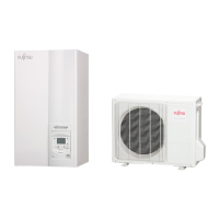
Heat pump, Split, single service
4.1 Configuration 1, 2, 3 or 4:
heat pumps with electric back-ups
DHW tank control (with electrical back-up) requires
the use of the DWH kit.
The control of 2 heating circuits requires the
installation of the 2nd circuit.
4.1.1
Hydraulic connections
F
In the case of a mixed DHW tank
Install the directional valve on the heating circuit (on
circuit 2 if it exists).
F
In the case of 2 heating circuits
With the 2nd circuit kit, the hydraulic module’s
circulation pump (CC1) must be moved and installed
in a box of the 2nd circuit kit (CC1).
4.1.2
Electrical connections
•
1 - Power supply to outside unit
Please refer to section (Electrical connections on
the outside unit side page 26).
•
2 - Interconnection between the outside unit and the
hydraulic module (See fig. 37, p. 28).
•
3 - Power supply to the electrical back-ups:
-
Connect the electrical supply for the back-ups
(terminals 9, 10 and 11) to the electrical panel. (see
fig. 37, p. 28).
•
4 - Outdoor sensor (see fig. 37, p. 28).
•
5 - Air thermostat and/or remote control (Option,
See fig. 38, p. 29).
•
6 - Contract with the power provider:
-
Connect the “Power Provider” contact to input EX5
or EX4. (see fig. 38, p. 29)
F
In the case of a mixed DHW tank
Please refer to the instructions supplied with the
DWH kit.
•
7 - Connect the directional valve to connector QX4,
(See fig. 38, p. 29).
•
8 - Connect the domestic water sensor to terminal
BX1 on the heat pump’s control panel (see fig. 38,
p. 29).
•
9 - Connect the back-up resistance to terminal 19
(Earth) and relay RP DHW to terminals 2 (L) and 4
(N). (see fig. 37, p. 28)
•
10 - Connect the electrical power supply for the
domestic water back-up (terminals 17, 18 and 19) to
the electric panel. (see fig. 37, p. 28)
F
In the case of 2 heating circuits
Please refer to the instructions supplied with the
second circuit kit.
11 - Circulation pump
12 - Circulation pump
13 - Mixer valve
14 - Initial sensor
() - Interconnection between RVS and AVS
F
In the case of a heated floor
Heated floor thermal safety fuse
•
20 - Thermal safety will stop the heat pump if the
temperature in the floor is too high.
4.1.3
Parametering the setting
•
Adjust the configuration: 1, 2, 3 or 4,Line5700.
•
Adjust the DHW programme (Line 1610 to 1661)
•
1 heating circuit
Adjust the heating curve slope.
Line 720
•
2 heating circuits
Adjust the heating curve slope.
Line 720 (Circuit 1)
Line 1020 (Circuit 2)
4.1.4
Special cases
Please consult us regarding any other installation
configuration
F
Parameter 5700
Configuration 1 : 1 heating circuit (See Figure page 48)
Configuration 2 : 1 heating circuit and DHW tank. (See Figure page 49)
Configuration 3 : 2 heating circuits (See Figure page 50)
Configuration 4 : 2 heating circuits and DHW tank. (See Figure page 51)
 Loading...