1.3 Specifications
Designation, Model ........................050 ....065 ....080 ....095 ....128 ....155
Nominal heating performances (outside temperature/ initial temperature)
Heat output
+7 °C / +35 °C - Floor heating system ....kW......5.....6,5.....8.....10,3....12,8....15,5
-7 °C / +35 °C - Floor heating system ....kW......4,8.....5,6.....7.....8,1.....11.....13,8
+7°C/+45°C-Lowtemperatureradiator .kW.....4,15 ....5,4.....6,2.....8,3.....9,7 ....13,3
-7°C/+45°C-Lowtemperatureradiator..kW.....4,05 ....5,1.....5,9.....7,3.....8,3.....11
Power absorbed
+7 °C / +35 °C - Floor heating system ....kW.....1,16....1,63....1,88....2,57....3,12....3,88
-7 °C / +35 °C - Floor heating system ....kW.....1,75....2,24....2,54....3,52....3,79 ....5,3
+7°C/+45°C-Lowtemperatureradiator..kW.....1,15....1,61....1,88....2,51....3,13....4,09
-7°C/+45°C-Lowtemperatureradiator..kW.....1,72....2,32....2,62....3,48....4,61....5,37
Nominal coefficient of performance (COP)
(+7°C/+35°C) ..................-......4,3.....4.....4,25.....4.....4,1.....4
Electrical characteristics
Supply voltage (50 HZ) ...............V .....230 ....230 ....230 ....230 ....230 ....230
Maximumstart-upcurrentoftheappliance ....A.....10,5....10,5....12,9....15,3....22,6....25,9
Nominalintensity ..................A......8,3.....8,3 ....10,6....11,7....16,7....20,6
Maximumcurrentoftheelectricalback-ups....A......13.....13.....13.....26,1....26,1....26,1
Poweroftheelectricalback-ups.........kW......3......3......3......6......6......6
Real power absorbed
-Bythefan ...................W......54.....54.....65.....103....2x103...2x103
-Bythecirculationpump............W .....113 ....113 ....113 ....113 ....151 ....151
Maximum power absorption
-Bytheoutsideunit...............W.....2600 ....2600 ....2930 ....3500 ....5150 ....5900
Hydraulic circuit
Maximum operating pressure ...........bar......3......3......3......3......3......3
Hydraulic system flow rate
4°C<Dt<8°C (nominal conditions)
-minimum .....................l/h .....540 ....600 ....860....1000 ....1380 ....1670
-maximum.....................l/h.....1100 ....1400 ....1700 ....2100 ....2700 ....3300
Various
Weightofoutsideunit ...............kg......40.....40.....44.....64.....98.....105
Noiselevelat5meters(outsideunit).......dB......39.....39.....40.....41.....40.....40
Weight of hydraulic module (empty/full of water). kg....52,5/77,5.52,5/77,5.52,5/77,5.52,5/77,5.52,5/77,5.52,5/77,5
Water capacity of the hydraulic module .......l......25.....25.....25.....25.....25.....25
Heating system operating limits
Exteriortempmini/maxi..............°C ....-15/+24..-15/+24..-15/+24..-15/+24..-15/+24..-15/+24
Initial max. heating water temperature
- Floor heating system ..............°C......45.....45.....45.....45.....45.....45
-Lowtemperatureradiator ...........°C......52.....52.....52.....52.....52.....52
Initial min. heating water temperature.......°C......8......8......8......8......8......8
Refrigeration circuit
Diameterofgaspipes.............inches......1/2.....1/2.....5/8.....5/8.....5/8.....5/8
Diameteroffluidpipes.............inches......¼ .....¼ .....¼.....3/8.....3/8.....3/8
Factory charge of refrigerant R410A ........g.....1250 ....1250 ....1700 ....2100 ....3350 ....3400
Maximum operating pressure ...........bar......45.....45.....45.....45.....45.....45
Minimum length of pipes ..............m......0......0......5......5......5......5
Maximum length of pipes* .............m......10.....10.....15.....20.....20.....20
Maximum length of pipes** .............m......20.....20.....30.....40.....40.....40
Maximumleveldifference**.............m......15.....15.....20.....30.....30.....30
* Factory charge of refrigerant R410A
** Taking into account the possible additional load of
refrigeration fluid R410A (see p. 22)
Installation and operating manual “1350-EN” 5
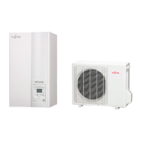
Heat pump, Split, single service
 Loading...