2-1
2. CABLE CONNECTION
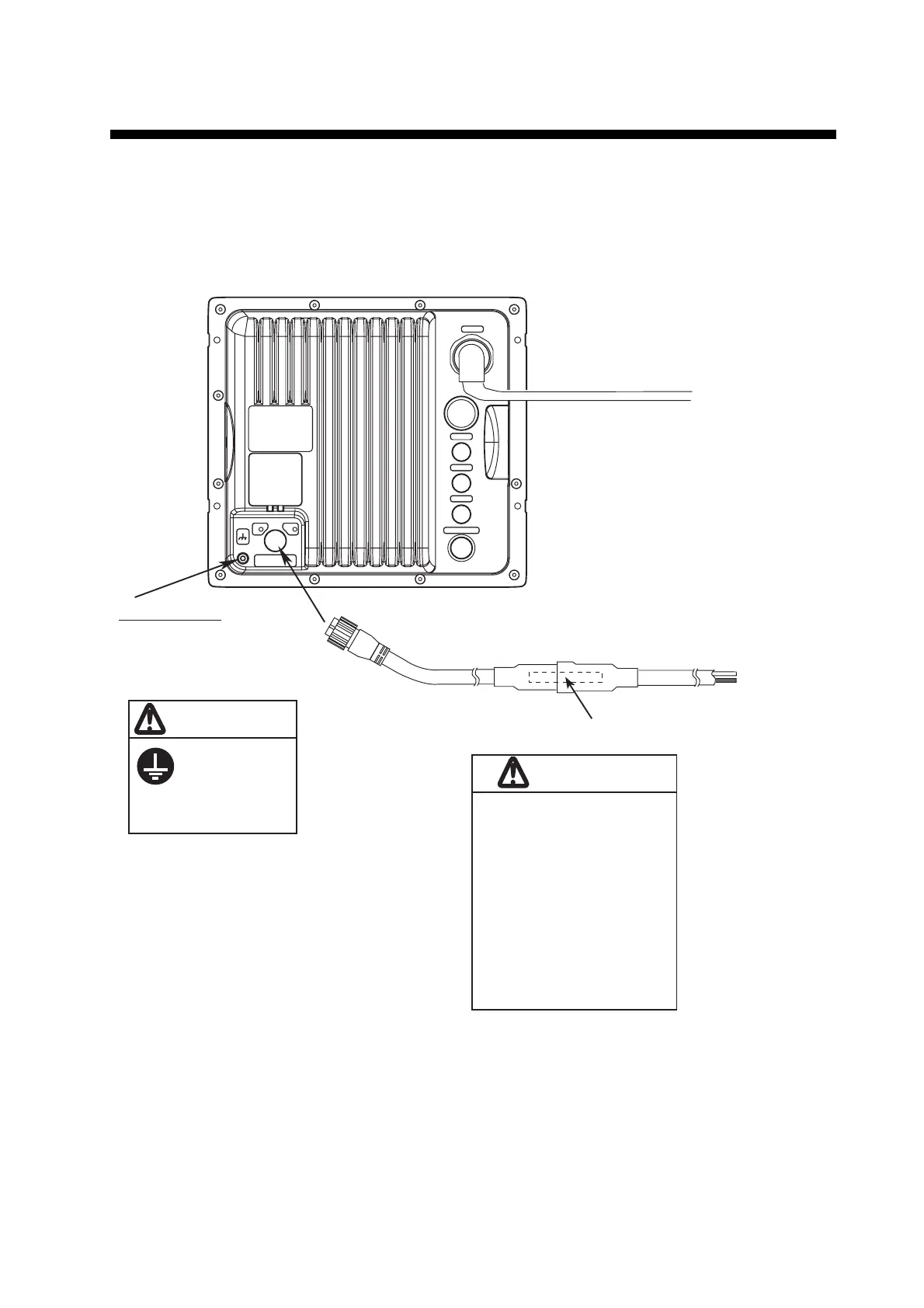
2.1 Standard Connection
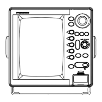
Connect all cables at the rear of the display unit.
Display unit, rear view
Antenna cable
MJ-B24LPF0002-xxx+R or
MJ-B24LPF0005-yyy+R
CAUTION
Ground terminal
Connect ground wire
between here and
ship's ground.
Ground the
equipment to
prevent
interference.
CAUTION
NMEA1
NMEA2
HDG
DJ-1
OPTION
12-24 VDC/ 8.0-3.8A
3 GND
1 + 2 -
USB
Power cable
MJ-A3SPF0017-050ZC
Fuse
To ship's power
distributor
+: White
-: Black
To antenna unit
(xxx: 100,150,200 or 300)
(yyy: 050,100,150,200 or 300)
The unit is shipped with 10A
fuse, which is for use with 12
VDC ship’s battery.
If your ship’s battery is 24
VDC, replace the 10 A fuse
with a 5A fuse, and attach the
appropriate label to the fuse
cover on the power cable.
Use of wrong fuse can
result in damage to the
equipment.
 Loading...