1. MOUNTING
1-8
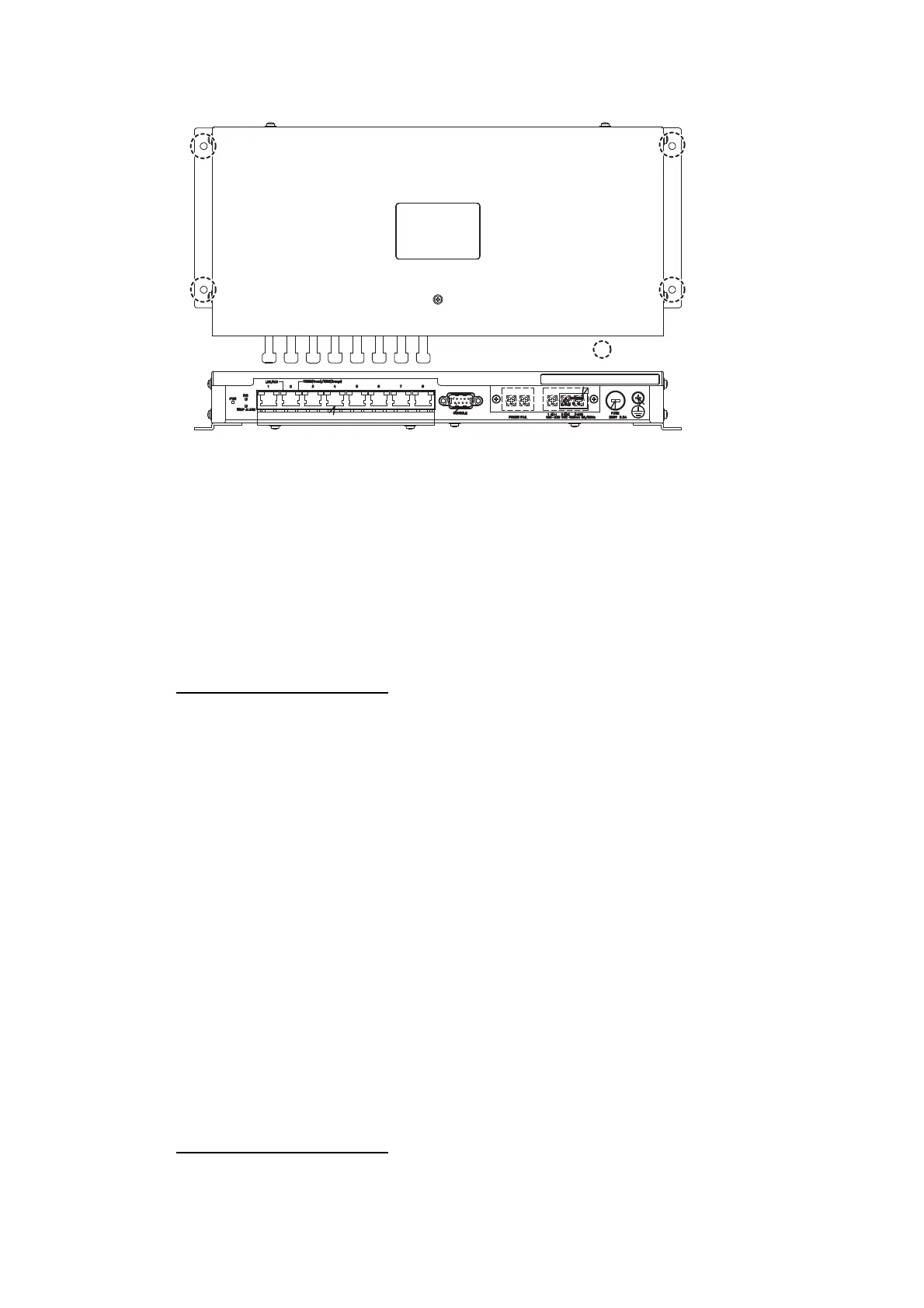
2. Fasten four self-tapping screws (4x20, supplied) to fix the unit.
1.6 Switching HUB (option)
Use this Switching HUB to connect the sensor network that complies with IEC 61162-
450 Ed.1. Do not use the HUB to connect a network other than shipboard LAN sensor
network. Note that a commercial PC cannot be connected in this network, other than
for the maintenance. The total length of all cables connected to the hub is 6 m.
For the mounting procedures, see the operator’s manual for HUB-100 (Pub. No.OMC-
35191).
Mounting considerations
When you select a mounting location, keep in mind the following points:
• Locate the adapter away from heat sources because of heat that can build up inside
the cabinet.
• The vibration should be minimal.
• Locate the equipment away from places subject to water splash and rain.
• Make sure that the ground wire is connected between the earth terminal on chassis
and the ship’s earth.
• Leave sufficient space at the sides and rear of the unit to facilitate maintenance.
• A magnetic compass will be affected if the adapter is placed too close to the mag-
netic compass. Observe the compass safe distances at the front of this manual to
prevent compass malfunctions.
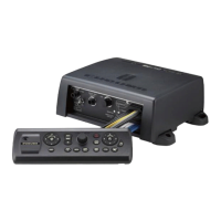
1.7 Radar Connection Box (option)
You can display signals from up to two external radars on the chart display by using
the RCB-002. The RCB-002 must be connected via the Gateway Network.
Mounting considerations
Keep the following points in mind when selection a mounting location:
 Loading...