2. WIRING
2-3
2.1 Processor Unit
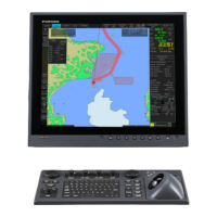
2.1.1 How to connect cables to terminals on the processor unit
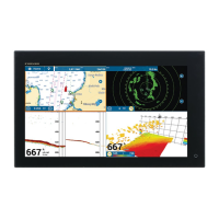
Use screws (M3×6, supplied) to
attach the wiring plate 1 and
wiring plate 2 to the processor
unit. Connect the cables to the
connectors at the front of the
processor unit, referring to the
following figure. After the con-
nection, bind cables to the ap-
propriate fixing metal with the
cable ties (supplied).
For the cables from the monitor unit (type: DVI-D/D SLINK5M/10M (MU-190 only),
DSUB9P-X2-L5/10M) and ground wire, connect them to the processor unit directly
(without fixing to a wiring plate). Tighten the fixing screws on these connectors to pre-
vent disconnection from the processor unit.
Note: Connect the cables so that they do not interfere with the opening or closing of
the DVD tray.
Cables connected at the wiring plate 1
Cables connected at the wiring plate 2
• USB cables from the control units
• Printer cable
• LAN cable (type: DTI-C5E350 VCV) from the HUB-3000
• LAN cable (type: FR-FTPC-CY) from the HUB-100/MC-3000S
• Power cable (Type: IEC60320-C13-L5M)
• LAN cable to the LAN3 port
Slide the plate toward
the unit to hide LED
and switches.
Wiring plate 2
Wiring plate 1
(DVI1: DVI-D/D S-LINK cable,
COM1: DSUB9P-X2-L cable or DSUB9P-X2-A-L cable)
COM1
Monitor unit
(DVI3: DVI-D/D S-LINK cable
or DVI-BNCX5-L2000 cable,
COM2: DSUB9P-X2-L cable)
DVI3
USB1
RCU-024/026
(TS-20-071-1 cable)
USB2/3
Optional control unit
RCU-024/026
(TS-20-071-1 cable)
HUB-3000
(DTI-C5E350 VCV
cable)
LAN1
LAN2
HUB-3000*/MC-3000S
HUB-3000: DTI-C5E350
VCV cable
MC-3000S:
FR-FTPC-CY
cable, max. 50 m length
DVI1
COM2
Cable clamp
Ground wire
(IV-2sq.,
local supply)
Power cable
(IEC60320-C13-
L5M cable)
For USB printer
LAN3
Not used.
DVI2
(DVI2: DVI-D/D S-LINK cable)
Monitor unit
Monitor unit
*: Use HUB-100 for IEC 61162-450 Ed.1 compliant network.
USB4
 Loading...