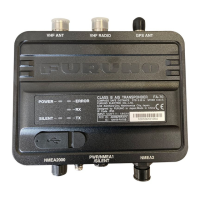
Why Furuno FA-70 cannot transmit/receive?
- TTanya MccoyAug 4, 2025
If your Furuno Marine Radio isn't receiving or transmitting, ensure the VHF antenna cable is firmly connected and inspect the VHF antenna and its cabling for any signs of damage.

 Loading...
Why Furuno FA-70 cannot transmit/receive?
If your Furuno Marine Radio isn't receiving or transmitting, ensure the VHF antenna cable is firmly connected and inspect the VHF antenna and its cabling for any signs of damage.
What to do if ERROR LED lights in orange on Furuno FA-70?
If the ERROR LED on your Furuno Marine Radio lights up in orange, it indicates a problem with the GPS antenna connection, the VHF antenna connection, or the MMSI. Please check that the GPS antenna is correctly connected, check that the VHF antenna is correctly connected, and confirm the MMSI.
How to fix no position data on Furuno FA-70 Marine Radio?
If your Furuno Marine Radio shows no position data, check the GPS antenna, the GPS antenna cable, and its connectors.
How to fix Furuno Marine Radio if it cannot turn on?
If you cannot turn on your Furuno Marine Radio, check the cable between the transponder and power for damage, check the power supply, and check the fuse.
| Brand | Furuno |
|---|---|
| Model | FA-70 |
| Category | Marine Radio |
| Language | English |
Manual usage, warranty, and modification guidelines.
Local regulations for product disposal.
Battery disposal guidance for EU and USA.
Warnings and precautions for operating the equipment.
Warnings and precautions for installing the equipment.
RF exposure limits and safe operating distances.
Welcome message and introduction to the FA-70.
Key capabilities and functions of the FA-70.
Important notes on MMSI and VHF splitter usage.
List of standard supply items for the FA-70.
Detailed list of included accessories and optional items.
Tools and materials needed for installation.
Mounting considerations and procedures for the FA-70 unit.
Guidelines for mounting and cabling the GPS antenna.
Guidelines for positioning and cabling the VHF antenna.
Mounting considerations for the optional power supply unit.
Diagram and instructions for connecting the FA-70 to other devices.
Steps to install the USB driver for PC connectivity.
Steps to install the PC software for configuring the FA-70.
Instructions for launching and closing the AIS Setting Tool software.
Explanation of the features and layout of the AIS Setting Tool.
Configuring ship static data, TX/RX mode, and silent mode.
Configuring port priorities, NMEA settings, and output modes.
Displaying channel, sensor, and GNSS status.
Monitoring current and past system alerts.
Monitoring data input from various ports.
Monthly checks for wiring, ground, antenna, and cabinet.
Procedure for replacing a blown fuse in the equipment.
Solutions for issues like no power, no transmission, or wrong data.
Performing transponder and GNSS system self-tests.
Overview of the PC software's menu structure.
Overview of the FA-70's menu accessed via an external display.
Detailed list of system alerts and troubleshooting steps.
List of NMEA2000 Parameter Group Numbers (PGNs) for input/output.
List of NMEA0183 data sentences for input/output.
Regulatory compliance information for the USA.
Regulatory compliance information for Canada.
General product type and transmitter technical details.
AIS receiver and VHF splitter technical details.
GPS receiver and interface details.
Power requirements and operating environment parameters.
List of items included in the FA-70 package.
Physical dimensions and mounting hole details of the FA-70 unit.
Physical dimensions of the GPA-C01, GPA-017, GPA-017S antennas.
Diagram illustrating connections between FA-70 and other system components.
Statement confirming compliance with EU directives.