www.furuno.com
ll brand and product names are trademarks, registered trademarks or service marks of their respective holders.
Installation Manual
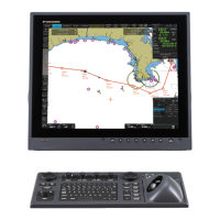
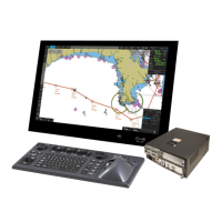
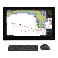
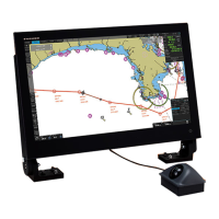
ECDIS
Model
FMD-3200/FMD-3300/FMD-3200-BB
(ELECTRONIC CHART DISPLAY AND INFORMATION SYSTEM)
SAFETY INSTRUCTIONS ................................................................................................ i
SYSTEM CONFIGURATION ........................................................................................... ii
EQUIPMENT LISTS........................................................................................................ iv
1. MOUNTING..............................................................................................................1-1
1.1 Monitor Unit........................................................................................................................1-1
1.2 ECDIS Control Unit/Track Control Unit ..............................................................................1-1
1.3 Processor Unit ...................................................................................................................1-4
1.4 Sensor Adapter MC-3000S/3010A/3020D/3030D (option)................................................1-6
1.5 Intelligent Hub HUB-3000 (option).....................................................................................1-7
1.6 Switching HUB HUB-100 (option)......................................................................................1-8
1.7 Radar Connection Box RCB-002 (option)..........................................................................1-8
2. WIRING....................................................................................................................2-1
2.1 Processor Unit ...................................................................................................................2-3
2.2 Monitor Unit......................................................................................................................2-13
2.3 Sensor Adapters (option).................................................................................................2-15
2.4 Intelligent HUB HUB-3000 (option) ..................................................................................2-33
2.5 How to Extend the Control Unit Cable (option) ................................................................2-34
2.6 Radar Connection Box RCB-002 (option)........................................................................2-38
3. ECN-303/304 (OPTION) ..........................................................................................3-1
3.1 How to Install the Console .................................................................................................3-1
3.2 How to Dismount the Rack for the Processor Unit.............................................................3-2
3.3 How to Connect External Cables .......................................................................................3-4
3.4 How to Mount the Rack for the Processor Unit..................................................................3-6
4. SETTING UP THE EQUIPMENT .............................................................................4-1
APPENDIX 1 JIS CABLE GUIDE .............................................................................AP-1
APPENDIX 2 ROD TERMINALS ..............................................................................AP-2
APPENDIX 3 RA/IF BOARD JUMPER VALUES .....................................................AP-8
PACKING LISTS ......................................................................................................... A-1
OUTLINE DRAWINGS ................................................................................................ D-1
INTERCONNECTION DIAGRAMS.............................................................................. S-1