EasyManua.ls Logo

Furuno LS-6100 User Manual

Furuno LS-6100
47 pages
To Next Page IconTo Next Page
To Previous Page IconTo Previous Page
Page #29 background imageLoading...
Page #29 background image
22
3. MAINTENANCE,
TROUBLESHOOTING
WARNING
ELECTRICAL SHOCK HAZARD
Do not open the equipment.
Only qualified personnel should work
inside the equipment.
3.1 Maintenance
Regular maintenance is essential for good
performance. Checking the items listed in
the table below monthly will help keep your
equipment in good shape for years to
come.
Checking
Item Action
Transducer
cable
Check cable for damage.
Power cable,
transducer
cable plug
Check that they are tightly
fastened. Refasten if
necessary.
Display unit
ground
Check for corrosion. Clean
if necessary.
Power supply
voltage
Check voltage. If out of
rating correct problem.
3.2 Cleaning the Display
Unit
Dust or dirt on the display unit can be
removed with a soft cloth. If desired, a
water-moistened cloth may be used. Use
special care when cleaning the LCD since it
scratches easily. Do not use chemical
cleaners to clean the display unit - they can
remove paint and markings.
3.3 Transducer
Maintenance
Marine life on the transducer face will result
in a gradual decrease in sensitivity. Check
the transducer face for cleanliness each
time the boat is dry-docked. Carefully
remove any marine life with a piece of
wood or fine-grade sandpaper.
3.4 Replacing the Fuse
The fuse in the power cable protects the
system from reverse polarity of the power
supply and equipment fault. If the fuse
blows, find the cause before replacing it.
Use only a 1A fuse (61NM-125V, 1A, or
equivalent FGBO-A, AC125V, 1A, Code No.
000-549-061). Using the wrong fuse will
damage the unit and void the warranty.
WARNING
Use the proper fuse.
Fuse rating is shown on the equipment.
Use of a wrong fuse can result in fire and
damage the equipment.
3.5 Battery Voltage Alert
A battery icon appears when the battery
voltage is too high or too low.
Battery icon and meaning
Icon Meaning
Voltage is lower than 10 VDC. If the
voltage goes below 9 V, the equipment
is automatically turned off.
Voltage is higher than 16.5 VDC. If the
voltage goes higher than 17.5 V, the
equipment is automatically turned off.

Other manuals for Furuno LS-6100

Question and Answer IconNeed help?

Do you have a question about the Furuno LS-6100 and is the answer not in the manual?
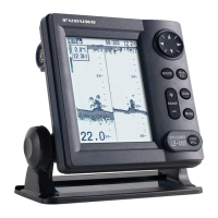
Furuno LS-6100 Specifications

General IconGeneral
Display4.5" LCD
Frequency200 kHz
Power Output600 W
Power Supply12-24 VDC
TypeFish Finder
Operating Temperature-15°C to +55°C
Beam Angle12°

Summary

Safety Instructions for the Operator

Operator Warnings

Critical warnings for the operator to prevent hazards like shock or injury.

Operator Cautions

Precautions to prevent equipment damage or dangerous situations during operation.

Safety Instructions for the Installer

Installer Warnings

Warnings for installers regarding electrical shock, water leakage, and proper cable usage.

Installer Cautions

Cautions for installers on transducer cable handling and compass interference.

1. OPERATION

1.1 Control Description

Explains the function of each button and control on the display unit.

1.5 Menu Operating Procedure

Explains how to navigate and operate the LS-6100's menu system.

1.15 Waypoints

How to record, output, and find waypoints.

1.19 Alarms

Details the six types of alarms and how to activate and configure them.

2. SYSTEM & INSTALLATION MENUS

2.1 System Menu

Settings for language, units, display options, and data sources.

2.2 Installation Menu

Settings for simulation, testing, memory, NMEA, and bottom level adjustments.

3. MAINTENANCE, TROUBLESHOOTING

3.6 Troubleshooting

Guide to identify and resolve common operational issues.

3.7 Diagnostics

How to run built-in diagnostic tests to check system components.

4. INSTALLATION

4.2 Thru-hull Mount Transducer

Instructions for installing thru-hull mount transducers, including location advice.

4.3 Transom Mount Transducer

Guidance on installing transom mount transducers on boats.

4.4 Inside-hull Transducer

Procedures for mounting transducers inside the hull.

4.5 Optional Triducer

Instructions for installing the optional triducer multisensor.

Related product manuals