Garmin G5 User's Manual
190-02072-00 Rev. B
30
Installation Manual
Installation ManualPilot's GuideIndex
1.5 G5 PINOUT
Use the information in this section (along with other applicable sections/appendices
in this document) to construct the wiring required for the G5 installation.
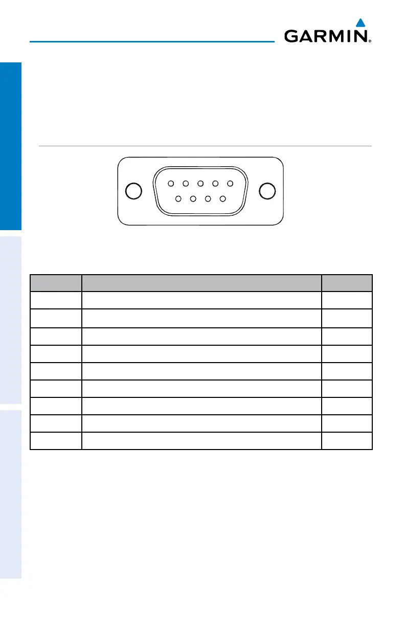
1.5.1 J51
51
96
Figure 1-14 J51 on the G5
Table 1-10 J51 Pin Descriptions
Pin Pin Name I/O
1 CAN-H I/O
2 CAN-L I/O
3 UNIT ID In
4 RS-232 RX 1 In
5 RS-232 TX 1 Out
6 SIGNAL GROUND --
7 AIRCRAFT POWER 1 In
8 AIRCRAFT POWER 2 In
9 POWER GROUND --
1.5.1.1 AIRCRAFT POWER
The G5 can operate using power from one or both inputs (AIRCRAFT POWER 1 and
AIRCRAFT POWER 2). The pins are internally connected using diodes to prevent current
from flowing between the two power inputs. AIRCRAFT POWER 2 is for connecting to
an alternate power source, such as on aircraft with two electrical buses.

 Loading...


